Technical paper: Extracting Energy From Piezofilm
Author: Ayush Jain, 2nd year, BTech, Electrical Engineering
College: Dayalbagh Educational Institute
1. ABSTRACT
While thinking of the renewable and eco-friendly source of energy the first thing which comes in our mind is solar energy, wind energy etc. but ,even, other clean energy sources are available with us –one of them is ‘Piezoelectricity’. On application of pressure, piezo-material generates voltage. In this paper, an idea is proposed for making a battery/charger using the principle of piezoelectricity. The designs and constructional details are given for a battery using the idea along with some derivations. Even some other applications of this idea are also provided in further sections. Practical implementation of this idea can serve society with a clean source of energy.
2. INTRODUCTION
The need of renewable and eco-friendly source of energy is increasing day by day as our coal reserves are depleting at a rapid rate. So it becomes necessary to find new energy sources. Some of them are solar, wind, biofuel energy etc. Piezoelectricity is also an eco-friendly way for generating voltage but due to high impedance very low current is generated and hence very low power. However now a days, piezofilms are used in parallel connections causing lesser equivalent impedance and hence somewhat improved power.
If somehow we are able to use these films for generating enough power at which day to day devices runs then it may replace the present available chemical batteries.
3. OLDER METHODS
There are some other methods by which piezofilms are used to generate electricity like- by the motion of crowd over floor, vehicles motion over roads. The best example of this is :- On October 6, 2009 the Hefer intersection along the old coastal road of Route 4 in Israel was the place where a piezoelectric generator was put to the test and generated some 2,000 watt-hours of electricity. The setup consists of a ten-meter strip of asphalt, with generators lying underneath, and batteries in the road’s proximity. The project manager, Dr. Lucy Edery-
Azulay said that expanding the project to a length of one kilo-meter along a single lane would produce 200 KWh, while a four-lane highway could produce about a MWh sufficient electricity to provide for the average consumption in 2,500 households.
3.1. DISADVANTAGE
- The method described above depends upon the number of vehicles passing over the road. Hence this method could be applied only at those places where enough traffic is present.
- Also in case of repairing of these films, underneath the roads, will lead to breaking of the roads.
- The larger area is required to place these films under road.
- We can’t vary the output as per our requirement.
4. IDEA
The idea in this paper is discussed here. Consider a completely closed box inside which several piezofilms are placed, rigidly in parallel connections. Also a gas is filled in this completely closed box. Now suppose that there is a heat source outside this box. Somehow the heat from source flows to the box due to which the box conducts and causes the gas inside to get excited up to such an extent that it starts applying pressure over rigidly supported piezofilms inside the box. This pressure causes films to generate voltage and hence we can get some power out of the box. This is the most basic explanation of the idea. The basic elements of this idea are pointed out below.
- A closed box.
- Gas and Piezofilms.
- A heat source.
4.1. ADVANTAGE
- As this idea does not require any involvement of vehicles hence it can generate electricity at any place and at same rate.
- The repairing of it is also very simple and doesn’t require any kind of breaking.
- The maximum area covered by it depends only on the size of box.
- This setup would be lighter, cheaper and compact.
- Variations in energy output can be made by varying the temperature of heat source.
4.2. DERIVATION
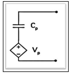
The first step is to understand the piezofilm characteristics as part of an electrical equivalent circuit. The piezofilm have internal capacitance and resistance. Hence it has some internal impedance. The fig. shows equivalent circuit for piezofilm.
Let a box of Volume =Vbox
Let an ideal gas in the box of mass =Mg
Let this gas occupy Volume =Vgas
Let a heat source heats up gas up to temperature =T
Let volume occupied by piezofilms = Vp
Output Voltage =VO
Let number of piezofilm=Np
P=Pressure applied over film
t= thickness of film (of order 10-6m)
A=area of one piezofilm
G3N = Piezofilm constant depends upon direction from where pressure is applied.
I. Relation between output Voltage and Temperature
From ideal gas equation, Pressure applied by gas, Pg=MgRT/Vg …(i)
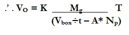
The output voltage generated by a piezofilm is governed by equation, VO =G3NPt …(ii)
Put (i) in (ii)
VO = K {MgtT/Vg} where, K= G3NR, which will be a constant for a given film and gas.
Also, Vbox= Vgas + Vp
Vp= At Np
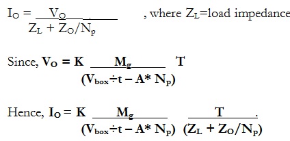
II. Relation between output Current and Temperature
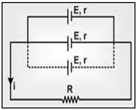
Let there are Np piezofilms each of them having ZO impedance
If all these films are placed in parallel, then the equivalent impedance of the system –
ZEq = ZO/Np
.’ . For parallel connections:-
The net output voltage will be equal to Output voltage of one film=VO.
III. POWER OUTPUT
So from these derivations it is clear that VO & IO varies linearly with temperature while PO varies parabolically with temperature.
4.3. PARTS OF BOX
In this section some important parts inside the box will be discussed. The parts of box are discussed below:-
I. PIEZOFILM
New copolymers of PVDF, developed over the last few years, have expanded the applications of piezoelectric polymer. Copolymer offers desirable shapes. Piezofilm is a flexible, lightweight, tough engineering plastic available in a wide variety of thicknesses and large areas. The fig. below shows the piezofilm available in market and as can be seen that the two electrodes plates are in parallel which leads to capacitive effect of piezofilm as discussed earlier.
II. BOX
The box is the outer casing carrying inside several piezofilms and gas. It consists of two parts- upper lid and lower portion.
- The upper lid is the only part which can be removed whenever required for testing, repairing etc. One side of lid contains some pointed out sharp extensions which are provided to make connections with the device. These sharp extensions are internally connected to electrode plates provided over the piezofilms. On both sides of the lid, near the bottom, some slots are present. These slots are provided in order to get fit to the hinges provided over the grid (explained next). The hinges are also provided at the side of these slots on the lid in such a manner that these hinges over lid and over grid just get parallel to each other and could be bolted to make box a completely closed box.
- The lower portion is simply the remaining portion of the box. On both top edges the slots are provided to fit the hinges over grid. Also at the bottom surface of this portion, some slots are provided and at side of these slots hinges are provided. These slots are provided to fit the grid’s hinges and bolt them with hinges at bottom of this box.
- After bolting up the hinges the box will become completely closed. Also it is important that the material used for the box must be strong enough to withstand pressure of gas as well as light weight like Aluminium alloys.
The fig. shows the box and its major parts.
III. GRID
It is important that the piezofilms remain rigid throughout the process i.e. it must not move from its required position. For this the grid can be used.
- A grid will be a collection of several piezofilms, necessary to develop enough energy.
- Grid is fixed to the box hence will help to fix the piezofilms at their place.
- It is necessary to place these grids in such a way that maximum pressure of gas could be transmitted to the piezofilms so that maximum energy could be extracted from them.
- Depending upon the direction of grid the value of constant, G3N, will be taken because this constant depends upon direction of pressure applied over piezofilms.
- The grids will contain several windows (piezofilm holder) inside which the piezofilms will be placed. These windows will keep the piezofilms at their positions. The windows will be opened from the front, top and bottom. The pressure of gas will be applied over piezofilms from the front. The piezofilm will enter into window from the top. These windows are welded to each other to form a grid.
- Several grids in parallel can be used to provide more power output. At the top and bottom sides of all grids hinges are provided as talked earlier. These hinges will fix the grid with the box and hence piezofilm will become fixed.
In the fig. only one grid and one box slot is shown just for simplicity. Also the slots at bottom of the lower portion of box are not shown. However there can be more than one grid in parallel.
IV. PIEZOFILM HOLDER
In the above fig. for the simplicity the piezofilms are directly shown in the grids. However we can’t do so as it may lead to vibrations of films at their positions. To avoid this we can use piezofilm holder discussed below.
- To fix the piezofilm in place we can use piezofilm holder. It will hold one piezofilm at its position. The thickness of these windows will be almost equal to the thickness of piezofilms with very small clearance. These windows are welded with each other.
- It remains open from the upper, front and bottom surface.
- The front surface is open so that the gas can apply pressure from front. Also the piezofilms are insulated from front using some kind of insulator between gas and piezofilms. The insulation will be required otherwise the high temperature of gas may affect the properties of piezofilms.
- Inside these windows, the pressure of gas from front and the reaction by window at back of piezofilm will compress it and some voltage will be generated.
- The upper and bottom surfaces are opened in order to make easier insertion of piezofilm inside these windows while manufacturing. A particular set of the piezofilms will be inserted from the upper surface of topmost window and this whole set will itself occupy its position in respective window.
V. GAS
It is the most important part of this idea as it is going to exert pressure over piezofilms. Hence the selection of suitable gas must be made by keeping in made the following point.
- Expansion of gas must be quick:- So that more pressure can be generated in lesser time and hence more power output.
- It must conduct heat:- For expansion of gas it is necessary that it must be conductive.
- It must not react with the piezofilm :- If reactive then it will damage the piezofilms.
- The piezofilm must not absorb the gas :- eg- PVDF absorbs 0.02% of H2O.
- It must not change its property with temperature:- Prediction of power output will become difficult if properties changes.
- Temperature of gas must become stabilize quickly:- Fluctuations in temperature will cause fluctuations in power output.
- Gas must not be hazardous for environment:- It is the aim of this idea to be eco-friendly in all possible way.
- Gas must not be explosive:- The high temperature and pressure inside may cause the gas to explode.
- Gas must be available in most economical way.
In the above derivations, gas was considered to be ideal, however, for real gases equations will get modified by taking van der waal’s constant (up to critical conditions).
- I have derived equations for real gases also which are very complex so I am not going to show them here. But the result from those equations comes out that the output current and voltage still changes linearly with temperature and power output still varies parabolicaly with temperature.
- So from here we conclude that the power output will not get much affected for real gases. Hence this idea can be applied for real gases with almost same results.
In the below fig. a complete setup is shown with invisible faces so that internal structure could be seen.
VI. HEAT SOURCE
It is heat which will make the gas to expand. So the heat source plays a vital role. Depending upon the heat source we can use this idea in ample number of ways. Some of the possible heat sources, about which we can think of, are given below. Along with these sources there applications are also shown some of which will be discussed in next section.
- There can be various ways of extracting the heat from source like direct conduction, radiation etc.
- In case of conduction we can directly connect a metallic bar to the box, which will conduct heat to gas. This method would lead to a bulky model.
- In case of radiation the box will be kept in a heated environment and will get heated and hence will heat the gas. This will be suitable at places where high temperature is generated as furnaces.
- We can use eddy currents also as a heat source. This method will be suitable in case of charging the mobile phones. Hence in this case, the idea could be used as a charger.
- We can also think of sun as a heat source by concentrating its heat over box on earth. Hence in this case, the idea can be used in similar manner as solar cells.
- Heat from engines in automobiles can also be used to heat the box and hence use it to supply power to the electrical devices in vehicles. Hence in this case, the idea can be used as vehicle battery.
5. APPLICATIONS
This idea can serve society with an eco-friendly source of energy in a much cheaper way which is the requirement of today’s world. In today’s world large amount of heat generated generally gets wasted like steam power plants, car engines, furnaces, heat from sun etc. Hence this idea will not only provide an eco-friendly source but will also help us to utilize the wasted heat energy. In this section some applications are given.
I. FURNACES
The furnaces are capable of generating huge amount of heat which can be radiated up to the box. Hence the power generated from the box can be transferred to other places in industries. So the application of this idea in industries can help them to cut down their need over the electricity from mains up to some extent.
II. AUTOMOBILES
This idea can be used in automobiles. The large amount of heat energy generated in the vehicle’s engine simply gets wasted. We can use this heat energy as our heat source. The power generated can be used for charging vehicle’s batteries and even we can provide direct supply to the devices in a vehicle. So this idea not only provides power but also helps to utilize the wasted heat energy.
III. CHARGER
We can use the concept of eddy currents to supply heat energy to the box. A setup can be mounted over this box. From the mains, current will be supplied to this setup leading to heat energy due to eddy currents which will act as heat source. So we can supply power from box to charge batteries of mobiles.
IV. ECO-FRIENDLY ENERGY SOURCE
If somehow we are able to concentrate enough heat energy from the sun then we can also use sun as the heat source. Hence it can act as an alternative for other eco-friendly energy source. We can use it in satellites for supplying direct power.
V. ROCKETS
For the lifting of rockets, the fuel is burnt. We can use our idea here by taking the heat from the burnt fuel and supply output from box to the rocket.
VI. ELECTRICITY GENERATION FROM DAMS.
We can use this idea for generating electricity from the dams. In this case the heat source will not be required. I have made a design for it (not shown here). In this case I have thought not to keep upper lid fixed but to make it oscillate by which we can get oscillating current.
- VII. SOME OTHE USES
- GAS LEVEL MEASURING DEVICE
The piezofilms can be fixed on the walls of the cylinders. The gas inside the cylinder will exert pressure over it so voltage will be generated. When the gas level will reduce, pressure will be decreased and hence voltage. We can mount a calibrated scale over the cylinder. Note no heat source will be required.
- WEIGHT MEASURING DEVICE
We can even use the piezofilms to measure the weights. The body will be placed over platform underneath it will be piezofilms. A calibrated scale will show the weight of the person.
6. CALCULATION
In this section I have done certain calculation which shows that this idea can be applied in practice. The data used here are taken from some tested experiments.
- Data:- Consider a(one) Piezofilm of, thickness, t = 52µm. Area, A = 155.55mm ×18.5mm.
If Pressure = 350 MPa is applied. Then it is able to generate =>
O/P Voltage=1600V. O/P Energy = 30.9 mJ.
- Calculation:- Consider that we want to get energy of 0.2MJ out of this box. From data above if the same sized piezofilms are used and if same pressure is applied then, No. of piezo-films used for generating 0.2MJwill be- Np= (0.2×10⁶)/30.9×10-3 ~ 6,666,666.
Volume of one piezofilm=1.5×10⁻⁷ m3. Hence the volume of 6,666,666 piezofilms = 1m3.
Consider that from heat source if temperature of 373K is provided. Consider volume of gas inside box to be, V=1m3.
So to generate 350 MPa of pressure the mass of gas (say nitrogen) required will be:-
M=PV/RT =350×106×1/296.8/373 ~ 103kg.
So from this calculation it becomes clear that we can generate enough amount of energy using this box. Although in this example the volume of box was considered to be around 2m3 (just for explanation) but we can vary box sizes depending upon where it will be put to use. Also the temperature can also be of different magnitudes. Here for simplicity of calculation I have taken simple values of volume of box. Hence this example shows that this idea can be implemented practically.
7. CONCLUSION
The piezofilm is a very simple device to operate as it has linear characteristic between output voltage and pressure and temperature as derived above. The calculations above also points out that this idea can be realised practically. In this paper very basic designs had been shown. The advantage of this idea, simple to construct, will make it, even, much useful. With the modifications in the designs we can make it useful in various ways. The most effective part of this idea is that it is purely eco-friendly. In this paper, I had used the cuboidal box as it will be simple in calculations and derivations. However we can think of other shapes also. This idea can provide a good eco-friendly way for getting energy and will even help to reduce the heat losses which are taking place in almost every machine. We can also conclude that this idea will help to make systems more efficient and cost effective. This paper can provide a new approach to deal with the problem of eco-friendly source of energy if looked upon. If proper attention is made over this idea then we can even implement it practically.
8. REFERENCES
http://en.wikipedia.org/wiki/Energy_harvesting#Piezoelectric
http://home.earthlink.net/~jimlux/energies.htm
http://www.engineeringtoolbox.com/individual-universal-gas-constant-d_588.html
Kumar, 2011, Electrical Power Generation Using Piezoelectric Crystal, International Journal of Scientific & Engineering Research, v.2, p.1-3
Piezoelectric effect, http://www.aurelienr.com/electronique/piezo/piezo.pdf
1999, Piezofilm technical manual, https://www.sparkfun.com/datasheets/Sensors/Flex/MSI-techman.pdf