Technical paper: Variable area jet nozzle for noise reduction using shape memory alloy actuators
Authors: Vimalraj.J, BE 3rd Year Aeronautical Engineering
Neeraja.P, BE 3rd Year Aeronautical Engineering
College: Madha Engineering College, Kundrathur, Chennai – 600069
ABSTRACT
The international community is demanding quieter, cleaner, and more efficient commercial transport aircraft. The aviation industry is responding with the development of new technologies towards achieving thosegoals. A significant reduction in noise and improved fuel consumption can be achieved by varying the area of commercial jet engine’s fan nozzle. A larger diameter at takeoff and approach can reduce jet velocity reducing noise. Adjusting the diameter in cruise, to account for varying Mach number, altitude, can optimize fan loading and reduce fuel consumption and emissions. Boeing recently tested a scaled variable area jet nozzle capable of a 20% area change. Shape Memory Alloy actuators were used to position 12 interlocking panels at the nozzle exit. A closed loop control system was used to maintain a range of constant diameters with varying flow conditions and to vary the diameter under constant flow conditions. Acoustic data by side line microphones and flow field measurements at several cross-sections using PIV was collected at each condition. In this paper the variable area nozzle’s design is described. The effect of the nozzle’s diameter on acoustic performance is presented. Flow field data is shown including the effects of the joints between the interlocking panels.
Introduction and Background
- The ability to control the area of the fan nozzle will enable the next generation of quieter, more efficient, and cleaner commercial jet engines. Current commercial turbojet engines have fixed fan nozzles with a design that is a compromise between efficient cruise operation an suitability for take off and landing.
- In general cruise operation would be more efficient with a smaller diameter nozzle; however the optimal cruise design point is often unacceptable for take-off as it will cause the engine to stall.
- Variable area fan nozzles (VAFN) avoid the current design compromises and allow optimal nozzle geometry for all flight phases. In addition to improved efficiency, varying the fan nozzle area, and hence the engine bypass ratio, is an extremely effective means of reducing community noise during takeoff and approach.
- Boeing is currently demonstrating practical and realizable VAFN technology for future aircraft. Concepts have been developed for such devices that are deployed using shape memory alloy (SMA) actuators. Shape Memory Alloys convert thermal energy into mechanical energy by way of a thermally induced micro-structural change in the material.
- The Austenitic phase of the material is stable at high temperatures, while the Martensitic phases are at equilibrium at low temperatures.
- A thermally induced change in the SMA micro structure results in a macroscopic actuator shape change.
- The Boeing VAFN concepts follow several years of successful design and test of SMA actuators to vary the geometry and shape of fan nozzles and other aerodynamic devices.
- In 2005 and 2006 Boeing conducted full-scale flight test and static engine test of Variable Geometry Flight test hardware for Variable Geometry Chevrons
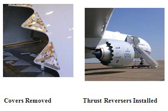
- Chevrons on a 777-300ER. These tests demonstrated the technology readiness of SMA Actuators for controlling shape of complex aero structures. The flight test hardware . Three SMA actuators were integrated into each chevron and were controlled via a simple PID controller to vary the nozzle geometry and correlate the geometry with fan exhaust noise.
- Many tests and analysis of VAFN have verified their benefit on commercial jet engines. The jet engine fan nozzle controls the engine back pressure and ensures the efficient conversion of exhaust gas potential energy to kinetic energy during the gases expansion to ambient pressures.
- Also opening up the exit area of the nozzle decreases the fan velocity and the associated jet noise. In addition a VAFN provides the ability to set the optimum area for the engine working point for a given flight condition, thus minimizing the thrust specific fuel consumption (TSFC) during that portion of the flight.
- Significant benefits can be achieved on commercial fan nozzles engines with area changes on the order of just 10-20%. The system described here takes a different approach from many of the hydraulic driven mechanical systems and wire SMA based concepts described in the literature.
- While in the past a majority of the SMA based concepts and designs for morphing structures have used wire actuators, the simplicity of Boeing’s VAFN’s monolithic flexure actuator is a great advantage.
- It avoids the difficulties of wire based designs that often rely on a complex set of mechanisms and clamps to heat the wire and then transfer the force
NOZZLE DESIGN
- Typically SMA actuator systems rely on passive return forces, in the form of springs or compliant structures to position the actuator at its Martensite position.
- The return forces act in opposition to the forces generated by the SMA elements when heated. When the SMA is heated it works against both the return forces and any external loads.
- When the SMA is cooled the return forces strain the SMA to its Martensite position. This concept requires a careful balance of the SMA elements, the return forces, and the external loads in order for the actuator to achieve the correct Martensite and Austenite positions.
- It can lead to over sized return forces, especially in the presence of unpredictable and varying external loads. This in turn can lead to oversized SMA actuators to work against the stronger return forces. In many aerospace applications the external loads can vary greatly in both magnitude and direction for a given actuator position, making precise balancing of the SMA and return forces even more difficult.
- Additionally the concept of passive forces opposing active SMA elements leads to systems the Variable Area Nozzle the loads on nozzle walls vary depending on mass flow, velocity, and nozzle shape. For this test it was required with a return actuation rate that is dependent on the cooling rate of the SMA, which is often much slower than the heating rate.
- In the case of that the nozzle be held at a defined minimum area under all loads, but also it must be able to hold a programmed area up to 20% larger as flow conditions changed.
- The antagonistic design was selected to give control authority in both the expand and contract directions. Forces in either direction could also be increased without relying on the cooling rate of the actuators
2.1 NOZZLE DESIGN
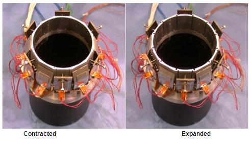
- A section of the nozzle . The fully open nozzle has an outlet diameter of 7 cm (2.75”). There are 12 interlocking Aluminum panels that make up the last 2.86 cm (1.125”) of the nozzle.
- SMA actuators designed to expand the nozzle when heated are attached to half the panels and SMA actuators design to contract the nozzle diameter when heated are attached to the other panels. the expand and contract actuators alternate around the nozzle.
- The interlocks and actuator forces are designed such that each panel’s edge stays in contact with the edges of the adjoining panels.A cross section schematic of an expanding section. A support structure is attached to a simple converging nozzle.
- Each of the interlocking panels has a curved inner surface with a shape matching the nozzle lines and an outside surface that is flat. Each of the panels is attached to the support ring by a small rectangle piece of thin steel. The steel holds the panel in alignment with the nozzle, while providing a hinge line that allows the panel to pivot away from the nozzle’s center.
- The steel shim provides a negligible amount of restoring force to the panel. A strain gage is attached to the steel and each panel’s tip displacement was correlated to the bending strain of the steel attachment piece.
- A SMA actuator made of Ni-40Ti(60% by wt. Nickel) was attached to each panel. The actuator base is attached to the support ring and the actuator tip is attached near the tip of each panel.
- A small resistive heater is bonded on the surface of each actuator.The `expanding actuators are trained to curve away from the center line of the nozzle when heated pulling the panel tip with it.
- The contracting actuators are trained to bend towards the center line when heated, pushing the panel tip into the nozzle flow.The actuators were 1.9cm wide (0.75”) x 4.4cm long(1.75”) and tapered from 2 mm (0.08”) thick at the base and 1 mm (0.04”) thick at the tip.
- The amount of preload on the actuator is adjusted by varying the distance between the panel and the actuator tip, either by changing the length of the tip screw for the expanding actuators or by placing shims between the actuator and panel for the contracting actuators. Photos for the full nozzle Variable area nozzle fully contracted and expanded 20%
2.2 Nickel Rich SMA Actuators
- One key to the variable area nozzle’s success is the SMA actuators. The simplicity of the monolithic flexure actuatoris a great advantage. It has a very small part count and provides a simple method of connecting to and positioningthe nozzle’s moving panels.
- Both the contracting and expanding actuators have the same dimensions, only the set Austenite shape varied. The actuator size was not optimized for this test and it is likely they could be reduced significantly .
- The variable area nozzle actuators are made of a nickel-richalloy, Ni-40Ti (60%Ni and 40%Ti by weight). It was only recently discovered that proper heat treatment of Ni-40 Ticould produce both super elastic and shape memory properties from the same ingot.
- Additionally with proper heat treatment, the transition temperatures could be varied from –55°C to 70°C. Recoverable strain up to 2.5% has been observed along with a strong two way effect and high cyclic stability without cold work.
- The more stable nickel-rich material allows for 1000s of actuator cycles with no degradation of performance.
2.3 Instrumentation and Control
- A simple feedback control system was used to regulate the nozzle’s exit area. During testing the nozzle diameter was estimated by measuring the strain of 6 of the steel pieces that connect the moving nozzle panels to the support ring.
- Prior to the nozzle test the strain measurements were calibrated to the measured nozzle diameter and linear coefficients for strain vs. nozzle diameter were determined.
- For these tests only one set of actuators, either expanding or contracting, were actively heated at any time and a common heater voltage was applied to the whole set.
- One set of actuators had to be near or below Mf at all times to prevent potential damage from both sets of actuators being Austenitic.
- Subsequent testing has shown this is not in both the fully expanded and fully contracted position.
3 TEST DATA
- The nozzle was tested in Boeing’s Quiet Air Facility in Seattle Washington. Fully expanded Mach number was varied up to 1.1.
- The control system was used to maintain aconstant diameter with varying nozzle flow conditions and to vary the diameter under constant flow conditions.
- Acoustic data by side line microphones and flow field measurements at several cross-sections using PIV was collected at each condition.
3.1 Variable area nozzle performance
- The nozzle was first controlled over a range of diameters while the nozzle flow was held constant at 0.9 Mach. The nozzle’s diameter and the controller set point vs. time are shown in Reasonably good control is demonstrated for both increasing and decreasing diameters.
- The large overshoot shown at about 100 minutes was caused by an unknown perturbation in the test or control system which resulted in an overheating of the contracting actuators for a short period of time.
- A constant nozzle diameter with varying nozzle conditionssuch as Mach and mass flow was also tested. The nozzlewas tested at 3 diameters with the Mach varying from 0 to 1.1.
- The Mach number shown on the graph is not actual recorded Mach data, but the nominal steady state value over that time period. Changes in the Mach number can clearly cause significant disruptions to the control of the diameter, although recovery to the set point is achieved on the order of a few minutes in most cases, which is a sufficient rate for most VAFN applications.
- Controller optimization could significantly reduce the size and duration of the disruptions.
3.2 Acoustic measurements
- The acoustic measurements were performed using a linear microphone array arranged in a line parallel to the jet axisat a distance of 33 D, the microphones were located every 5° between 90° and 160°.
- All results shown in this paper are scaled for velocity and propagation radius with reference to 286.7 m/s (Mach 0.9 at 20°C) and 100 D.
- A nested spiral phased array with 157 microphones and a diameter of about 1m was used to measure strengths of acoustic sources in the jet. The whole array was placed 1 m away from the jet axis with its origin located about 0.3 m downstream of nozzle exit.
- The angular variation of the overall sound pressure level(OASPL) obtained from the sideline microphone data covering the aft quadrant is given.
- The directivity curve corresponding to the circular case shown with the blue line has the common subsonic mixing noise characteristic with gradual increase to a maximum at an angle of about 155°. Increased nozzle area lowers the exit velocity necessary for the same thrust.
- Since the noise is directly related to the exit velocity with a power of about 8 in average and related to the nozzle diameter with a power 2, there is a net benefit from increasing the nozzle diameter. With the first diameter increase to 67mm (2.65 in) the noise benefit is around 2 dB at all directions. At the largest diameter of 70mm (2.75 in) the acoustic directivity changes with an apparent increase at the lower angles and a very small benefit at the maximum radiation angle.
- This is probably due to flow separation in the nozzle at the panel’s hinge 0line and/or an increase in the turbulence levels in the shear layer caused by the slots that occur when the nozzle is at the widest exit area.lower angles and a very small benefit at the maximum radiation angle.
- This is probably due to flow separation inthe nozzle at the panel’s hinge line and/or an increase in the turbulence levels in the shear layer caused by the slots that occur when the nozzle is at the widest exit area ,the noise source maps obtained from the acoustic phased array are shown for source frequency of2 kHz, corresponding to Strouhal number of 0.5.
- The colored contours represent the minimum diameter, case SPL distribution radiated from the jet as seen by the array.The minimum SPL shown was chosen to be 8 dB down from the maximum to eliminate side-lobe noise.
- Thecomparison between the nozzle diameter cases is made bythe contour lines corresponding to a particular constant SPLvalue of 82 dB for the 2 kHz frequency.
- The solid contour line is for the minimum diameter nozzle flow compared to two other diameters shown by the dashed and dotted lines.When the nozzle is opened to 67mm (2.65”) the source extent is significantly reduced at first, as shown by large dashed line.
- However, further opening to 70mm (2.75”)moves the source peak location closer to the nozzle exit and the extent is increased. This is compatible with the results obtained from the sideline data. The flow character change by possible partial separation could be the source of such behavior.
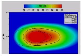
Noise source mps for 3 nozzle diamters
- The jet behavior in the near field region at each nozzle configuration
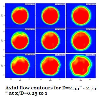
- The time averaged velocity fields were obtained from an ensemble of about 200 samples at each cross-section. The flow was captured at varying nozzle diameter from D = 2.55 to 2.75 inches with 0.1 in increments. The PIV setup used in this study was functionally similar to the one used in Alkislar et al the results are shown at all axial locations and at minimum, median and maximum diameter nozzle openings. In these figures the axial velocity is shown in colored contours, and the external (low speed) boundary of the shear layer is shown with the black solid line.
- At the closest cross-section of x/D = 0.25, there is some difficulty in measurements due to laser light reflections from the top of the nozzle at 12:00 sector. When the nozzle is fully closed the flow is quite axi symmetric with circular shear layer outer boundary. When the nozzle is opened to median diameter, the flow still seems to hold its symmetry with some minor effects on the shear layer, evident with the kinks at nozzle section intersection
locations , at the maximum nozzle diameter, however, the flow becomes largely affected at the intersection regions of the shear layer. - The longitudinal cavities appearing between the nozzle sections create local axial vorticity that ultimately changes the shear layer characteristics, causing the flow to deviate from axial symmetry. Another possibility is evident from the abrupt change in the acoustic characteristics. It suggests that there might be a separation partially or fully around the inner surface of the nozzle due to sudden enlargement of the nozzle area.
- 4 Future Plans
- .Currently Boeing is developing and testing full scale Variable Area Fan Nozzle designs that utilize an array of SMA monolithic actuators to morph or reshape the carbon composite nozzle structure. The morphing increases the exit diameter while eliminating the discontinuities created by the rotating of solid panels, as was done in this study,therefore maintaining attached flow. Additionally seals will be used to close out the gap between panels which appears to have increased noise in the subscale test.
5 Conclusions
- A subscale proof of concept demonstration of a variable area jet nozzle was demonstrated using SMA actuators configured in an antagonistic design. A simple PID feedback controller maintainedconstant diameter with varying nozzle flow parameters and vary diameter control with constant flow conditions. Area control of 0% to 20% expanded area at Mach rates up to 1.1 was shown.
- Acoustic data by side line microphones showed asignificant reduction in nozzle noise when the area was expanded. Flow field measurements at several cross-sections using PIV showed significant effects from the joints between the interlocking panels.
References
J.H. Mabe, R.T. Ruggeri, E. Rosenzweig, and C. Yu, “NiTinol Performance Characterization and Rotary Actuator Design”, SPIE Smart Structures and Materials 2004, SPIE-5388-11, San Diego CA, March 2004.
J. Mabe, R. Ruggeri, F. Calkins, “Characterization of Nickel-rich NiTinol Alloys for Actuator Development”, The International Conference on Shape Memory and Super elastic Technologies, Pacific Grove, CA, May 7-11, 2006
J.H. Mabe, F.T. Calkins, G.W. Butler, “Boeing’s Variable Geometry Chevron: Morphing aero structure for jet noise reduction,” 47nd AIAA Adaptive Structures Conference, AIAA-2006-2142, Newport RI, May 2006.