Title: A Survey on Image Resolution Enhancement Techniques
Author (s): Dr. Raja Murali Prasad
Institute: Vardhaman College of Engineering, Hyderabad.
ABSTRACT-Satellite images will be suffered from speckle noise due to the environmental disturbances such as fog and haze, which will degrade the visual quality of the images. In order to find the location or the persons, someone needs to enhance these speckled satellite images to improve the perceptual quality of images. Here, a hybrid wavelet transforms and interpolation (HWTI) based algorithms has been proposed to super resolute the low resolute satellite images. Interpolation is used to improve the high frequency sub bands and HWT is used to enhance the high frequency sub bands to obtain the high resoluted (HR) images from the low resolution (LR) images. Simulation results shows that the proposed algorithm has given better de-speckled results over conventional enhancement techniques such as Bi-linear interpolation, wavelet zero padding (WZP) and even that of discrete wavelet transform (DWT) in terms of peak signal to noise ratio (PSNR) and mean square error (MSE).
I. INTRODUCTION
Recent years, there is a rapid growth in satellite imaging due to the demand in satellite applications such as weather forecasting, astronomy and geographical data. These images were captured with the satellite sensors which are ranging from low resolution to high resolution for collecting the desired data into images. Satellite imaging applications have been increasing day by day due to the demand in applications like agriculture, oceanologoy, regional planning, geology, landscape, biodiversity conservation, forestry, cartography, meteorology and warfare etc.,[1]. In order to analyze the satellite images, we need HR satellite images but these images will be suffered from many factors such as absorption scattering while capturing it through the satellite sensors. These noise elements will create some serious issues for further processing of images in practical applications such as marketing, artificial work, computer vision and also in many fields. Hence, to improve the quality of these images by enhancing the visual quality is an important and challenging task. One must consider several factors to select a speckle reduction algorithm for satellite imagery.
• A digital camera must apply a noise reduction algorithm in a fraction of a second.
• Whether forfeiting few real information is acceptable if it allows more distortion or noise to be removed.
Interpolation is a one of the widely used method for enhancing the image, which is very simple and more popular. These techniques have been cauterized into three parts: 1. nearest neighbor interpolation, 2. Bi-linear interpolation, 3. bi-cubic interpolation. However, these methods were not suitable for all images and also gives more dark or brighter pixels after interpolating the LR images, which in results the quality degradation. There are two types of image resolution enhancement methods, those are: one is Spatial domain, which applies directly on to the pixels i.e., doesn’t need to transform the image into other form such as gray level transformation, histogram equalization, neibourhood pixel adjustment etc.,[2] and [3]. And second Transform domain, which transforms the LR image into frequency domain and then applies any algorithm to enhance the LR image to HR image such as discrete Fourier transform (DFT) [4], discrete wavelet transform (DWT) [5] and discrete cosine transform (DCT) [6].High frequency details of an image will be preserved by an adaptive anti-aliasing algorithm based on the wavelet Fourier transforms (WFT) [7] and adaptive wavelet shrinkage, which removes aliasing artifacts by shrinkage coefficients. Most effective satellite image enhancement is done by using dual tree complex wavelet transform (DT-CWT) with bicubic interpolation given in [8] and cycle spinning concept is also used to enhance LR image to HR image by merging with CWT or DWT [9] and [10]. However, all the above algorithms have been suffering from lack of reliability, much complex to implement in real time world. Hence, to overcome the drawbacks of existing methods a novel resolution enhancement scheme has been proposed using DUWT with bilinear interpolation method.
II. EXISTING METHODS
In the past decades, there are several algorithms have been developed to enhance a LR image with improved performances. In 1974 Hall et. al. proposed a gray level transformation in [11], this transformation has been used for image enhancement as well as for normalization process. Later on several filters have been developed in [12-15] and for enhancing and denoising the LR images. The author in [16] has proposed a fast filtering algorithm for enhancing the LR image, which performs noise smoothing and makes the minimum modifications in the original LR image to obtain HR image by taking the four sub images weighted combination along four major directions. In [8], [9] and [17], a satellite image resolution enhancement method based on DT-CWT, in which the LR image is decomposed into several high frequency bands. Then after these sub bands are interpolated and finally, inverse DT-CWT is used to combine these modified sub bands to get the HR image.
Fourier Transform (FT) and Short Term Fourier Transform (STFT) are the current methods used in the field of image processing. However due to severe limitations imposed by both the Fourier Transform and Short Term Fourier Transform in analyzing signals deems them ineffective in analyzing complex and dynamic signals. FT has a drawback that it will work out for only stationary signals, which will not vary with the time period. Because, the FT applied for the entire signal but not segments of a signal, if we consider non-stationary signal the signal will vary with the time period, which could not be transformed by FT. and one more drawback that we have with the FT is we cannot say that at what time the particular event will has occurred. In STFT, the window is fixed. So, we this window will not change with the time period of the signal i.e., for both narrow resolution and wide resolution. And we cannot predict the frequency content at each time interval section. To overcome the drawbacks of STFT, a wavelet technique has been introduced with variable window size. Wavelet analysis allows the use of long time intervals where we want more precise low-frequency information, and shorter regions where we want high-frequency information.
In order to substitute the shortcomings imposed by both the common signal processing methods, the wavelet technique is used. The wavelet technique is used to extract the features in an image by processing data at different scales. The wavelet technique manipulates the scales to give a higher correlation in detecting the various frequency components in an image. In fig.1 it is shown that the comparison of FT, STFT and wavelet transform by considering an example input signal and how the analysis of transformation techniques will apply to get the frequency information of input signal. We can observe that in wavelet analysis the graphical representation shows that the wavelet has more number of features than the FT and STFT. Wavelet is also called as multi resolution analysis (MRA).
2.1. Discrete Wavelet Transform (DWT)
Discrete Wavelet Transform (DWT) is a modified version of Continuous Wavelet Transform (CWT). DWT principles are very similar to the CWT however the wavelet scales and positions are based upon powers of two.
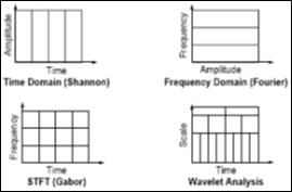
Fig.1. Comparison of FT, STFT and Wavelet analysis of a signal
The wavelet function is defined as follows:
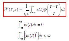
The basic principle of DWT is to pass the input signal through a group of filters i.e., low pass and high pass filters to get the low frequency (LF) and high frequency (HF) of source signal. Low frequency contents include LL and these coefficients are known as the approximation coefficients [18]. This means the approximations are obtained by using the high scale wavelets which corresponds to the low frequency. The high frequency components which are known as LH, HL and HH of the signal are called the details which will be obtained by using the low scale wavelets which corresponds to the high frequency. The process of DWT filtering includes, first the signal is fed into the wavelet filters. These wavelet filters comprises of both the high-pass and low-pass filter. Then, these filters will separate the high frequency content and low frequency content of the signal. However, with DWT the numbers of samples are reduced according to dyadic scale. This process is called the sub-sampling. Sub-sampling means reducing the samples by a given factor. Due to the disadvantages imposed by CWT which requires high processing power [11] the DWT is chosen due its simplicity and ease of operation in handling complex signals.
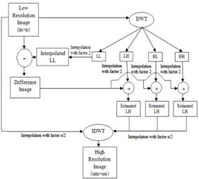
Fig2. Existing DWT-RE block diagram
Fig2 shows the block diagram of existing DWT-RE method. First, the LR image is given as an input to the DWT to decompose it into four sub bands LL, LH, HL and HH, which known as approximation, horizontal, vertical and diagonal coefficients and last three sub bands are also called as detail coefficients. These sub bands size will be half of the LR image due to that the DWT has a decimation property. Hence we need to interpolate it to further operate it with the LR image.Now, the LL sub band will be interpolated to subtract from the original image i.e., LR image, after this operation a difference image will be obtained. This difference image will be added to the high frequency sub bands LH, HL and HH to improve the high frequency sub bands information. In order to perform addition for these sub bands, we need interpolation to increase the size of decimated sub bands because, the size of difference image equals to the LR image which is an original image. After performing this operation, the estimated or modified LH, HL and HH will be obtained. The after do the interpolation for LR image with a factor ofα⁄2, where the parameter α is a interpolation factor, and do the same for even estimated LH, HL and HH also. Finally, apply inverse DWT to these four sub bands to get the super resolute image i.e., HR image.
However, this approach has been suffering from the decimation property of DWT, because when we apply the DWT decomposition to LR image, it will decompose the image into four sub bands with reducing the size of it to the half of LR image. Here we need to enhance the image quality but due to this decimation we lose some original information while processing with DWT. Therefore, to improve the performance of RE algorithm further, someone needs to gain the lost information and add it with high frequency sub bands to get the modified coefficients.
PROPOSED TECHNIQUE
This section gives a brief description about the proposed RE method using HWTI approach with interpolation. Fig.3 shows that the proposed block diagram which includes both decimated and un-decimated wavelet transforms for improving the image quality. First, the input LR image will be given as an input to the decimated as well as un-decimated wavelets to decompose them into sub bands. Then we will get the low frequency and high frequency sub bands with the size of half of the LR image and equals to the LR image. Now, added the high frequency sub bands of both wavelet transforms, by using interpolation for increasing the size of decimated LR image sub bands to obtain the new or estimated high frequency sub bands i.e., estimated LH, HL and HH. Finally, these sub bands and LR image were interpolated with the factor of α/2 and applied inverse DWT to get the super resolute image with more improved quality than the DWT method in terms of PSNR, SSIM and MSE.
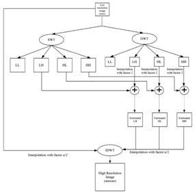
Fig3. Proposed block diagram of HWT with interpolation method
3.1. Quality metrics
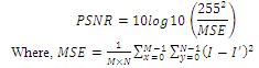
This section deals with the image quality assessment (IQA) metrics to measure the quality of resolute images. The IQA metrics used in this project are peak signal to noise ratio (PSNR) and mean square error (MSE).
PSNR is defined as follows:
IV. SIMULATION RESULTS
Experimental results have been done in MATLAB 2014a version with 4GB RAM for high speed CPU performance and tested several satellite images taken from various satellite databases. Fig4 shows that the original LR image which has been taken for testing, bilinear interpolated, bicubic interpolated and wavelet zero padded outputs. The output of DWT-RE method and wavelet decomposed images has shown in fig5, in which the quality of the image has been increased. Fig6 shows that the proposed HWTI-RE algorithm, we can observe that the proposed approach has given better resolute image compared to the DWT-RE method. The quality metrics used for IQA has discussed in section III, fig7 shows that the PSNR comparison of conventional interpolation, wavelet zero padding (WZP) and DWT-RE with proposed HWTI-RE method. Here, bilinear interpolation is used as a conventional interpolation scheme, which has got the PSNR of 22.978 dB, WZP has performed even better than the bilinear interpolation with an improved PSNR of 29.34 dB, further enhancement has done by using DWT-RE method which has got a PSNR of 34.9303 dB and finally, our proposed scheme performance is much superior to all the above mentioned RE algorithms with a PSNR of 35.2336 dB. MSE is inversely proportional to the PSNR i.e., if the PSNR in high then the MSE will be lesser. Another quality metric SSIM has shown in fig8, also it has shown that our proposed scheme is far better than all conventional RE algorithms in terms quality metrics and even visual perception.
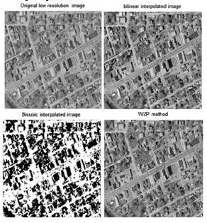
Fig4. Original LR image, Bilinear, Bi-cubic and WZP method
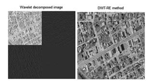
Fig5. DWT-RE method
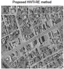
Fig6. Proposed HWTI-RE method
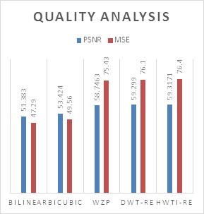
Fig7. Comparison of PSNR and MSE values
REFERENCES
[1] Goetz J. A. H. F.,G. Vane, J.E. Solomon, B.N. Rock,“Imaging Spectrometry for Earth Remote Sensing,” Science, 1985, vol. 228, pp. 1147-1153.
[2] X. Li and M. Orchard, “New edge-directed interpolation,” IEEE Trans. Image Process., vol. 10, no. 10, pp. 1521–1527, Oct. 2001.
[3] L. Zhang and X. Wu, “An edge-guided image interpolation algorithm via directional filtering and data fusion,” IEEE Trans. Image Process., vol. 15, no. 8, pp. 2226–2238, Aug. 2006
[4] W. K. Carey, D. B. Chuang, and S. S. Hemami, “Regularity-preserving image interpolation,” IEEE Trans. Image Process., vol. 8, no. 9, pp. 1293–1297, Sep. 1999.
[5] Y. Piao, I. Shin, and H. W. Park, “Image resolution enhancement using inter-sub band correlation in wavelet domain,” in Proc. ICIP, vol. 1,pp. I445–I-448,2007.
[6] Q. Sun and J. Tang, “A new contrast measure based image enhancement algorithm in the DCT domain,” IEEE International Conference Systems, Man and cybernetics, vol. 3, pp. 2055-2058, October 2003.
[7] Eunjungchae, Wonseokkang, Joonkipaik, “Spatially Adaptive Antialiasing for Enhancement of Mobile Imaging System Using Combined Wavelet-Fourier Transform,” IEEE transaction on consumer electronics vol 59, 4Nov 2013.
[8] N.Kundeti, H.K.Kalluri, S.V.Krishna,”Image Enhancement Using DTCWT Based Cycle Spinning Methodology,” IEEE Conference On Computational Intelligence andComputing Research, 2013.
[9] H. Demirel and G. Anbarjafari, “satellite image resolution enhancement using complex wavelet transform,” IEEE Transactions on Geosciences and Remote Sensing Letters, Vol. 7, pp. 123–126, 2010.
[10] A.Temizel and T.Vlachos, “Wavelet Domain Image Resolution Enhancement Using Cycle Spinning,” Electronics Letters, vol.41.pp119-121, 2005.
[11] E. Hall, “Almost Uniform Distributions for Computer ImageEnhancement”, Computers, IEEE Transactions, Volume: C23,Page(s):207-208,1974.
[12] H. Keshavan, M. Srinath, “Interpolative models inrestoration and enhancement of noisy images”, Acoustics,Speech and Signal Processing, Volume: 25, Page(s): 525-534, 1977.
[13] J. Lee, “Digital Image Enhancement and Noise Filtering byUse of Local Statistics”, Pattern Analysis and MachineIntelligence, Volume: PAMI-2, Page(s): 165-168, 1980.
[14] V. Algazi, “FIR Anisotropic filters for image enhancement”,Acoustics, Speech, and Signal Processing, Volume: 11, Page(s): 2471-2474, 1986.
[15] D. Keren, S. Peleg and R. Brada, “Image sequenceenhancement using sub-pixel displacements”, ComputerVision and Pattern Recognition, Page(s): 742-746, 1988.
[16] C. Hegang, L. Kaufman and J. Hale, “A fast filteringalgorithm for image enhancement”, Medical Imaging,Volume: 13, Page(s): 557-564, 1994.
[17] H. Demirel, G. Anbarjafari, “Satellite Image ResolutionEnhancement Using Complex Wavelet Transform”,Geoscience and Remote Sensing Letters, Volume: 7, Page(s):123-126, 2010.
[18] H. Demirel, G. Anbarjafari, “Discrete Wavelet TransformBasedSatellite Image Resolution Enhancement”. Geoscienceand Remote Sensing, Volume: 49, Page(s): 1997-2004, 2011.
To download the above paper in PDF format Click on below Link: