Title: – Magnetic Fuel Energizer
Author: – Himanshu Somvanshi, 3rd year Mechanical Engineering.
Himanshu Singh, 3rd year Mechanical Engineering.
Santosh Shinde, 3rd year Mechanical Engineering.
College: – K.K. Wagh Institute of Engineering Education & Research, Nasik.
ABSTRACT
Fossil fuels leave a natural deposit of carbon content that choke carburetor, fuel injector, leading to decrease the mileage and wastage of fuel. In this era of increasing fuel prices, here a device called ‘Fuel Energizer’ helps us to Reduce Petrol /Diesel /Cooking gas Consumption up to 28%, or in other words this would equal to buying the fuel up to 28% cheaper prices. When fuel flow through powerful magnetic field created by Magnetizer Fuel Energizer, The hydrocarbons change their orientation and molecules in them change their configuration. The Result is Molecules get realigned, and actively into locked with oxygen during combustion to produce a near complete burning of fuel in combustion chamber. This seminar focuses on the idea of newly evolved term ‘Magnetizer Fuel Energizer’, its working principle, components, installation technique, Comparison between the Catalytic Converter and the Magnetizer, its utility, benefits, recent developments etc.
INTRODUCTION
Most fuels for internal combustion engine are liquid, fuels do not combust until they are vaporized and mixed with air. Most emission motor vehicle consists of unburned hydrocarbons, carbon monoxide and oxides of nitrogen. Unburned hydrocarbon and oxides of nitrogen react in the atmosphere and create smog. Smog is prime cause of eye and throat irritation, noxious smell, plat damage and decreased visibility. Oxides of nitrogen are also toxic. Generally fuels for internal combustion engine are compound of molecules. However these molecules have not been realigned, the fuel is not actively inter locked with oxygen during combustion, the fuel molecule or hydrocarbon chains must be ionized and realigned. The ionization and realignment is achieved through the application of magnetic field created by ‘Fuel Energizer’. An objective of the Magnetic fuel energizer is to provide significantly improved molecular excitement and turbulence in a petroleum/diesel based fuel so that re-polymerization is more effectively resisted and improved fuel efficiency is achieved.
WHAT IS MAGNETIC FUEL ENERGIZER?
A magnetic fuel energizer is a device which is used to alter atomic construction and organize fuel molecules (fuel quality) so that proper combustion happens in I.C. engine/automobile. As magnetic field is applied to ionizing a fuel feed to the combustion chambers which enhance combustion process and gives out lower emission and improved mileage6. Magnetic field applied to fuel line atomizes fuel properties which get adhere to more oxygen molecules and enhances fuel air mixture. This provides peak engine performance while extending engine maintenance and filters change intervals thus reducing harmful emissions and carbon deposits & also we can ensure more complete combustion. Basic concept of magnetize fluid: In 1989, Hans Dehmelt of university of Washington was awarded noble prize in physics for his great contribution in fundamental properties of electrons. According to that electrons having ability to store up energy within itself similar to flywheel called spin. When it provides small amount of magnetic field, it absorb the energy and properties will change which is based on the below theories i.e. Chemistry theory – Covalent bond, Physics theory – Barnett effect, Math’s theory – Quantum mechanics.
Chemistry theory: Particles are made up of number of atoms. In Fig. 1 shows an atom having equals number of Proton & electron in neutral charge, if greater number of electrons is there then –ve charge is obtained & if reversed then +ve charge is obtained. We are familiar with construction of fuel molecule (C–H bond). Each electron has two movements 1) Spin & 2) orbital movement which results in mixing of fuels.
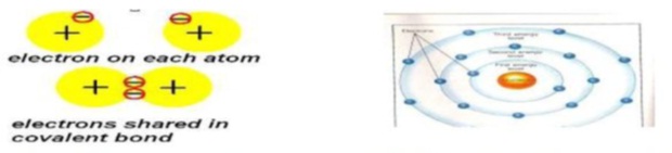
Fig. 1 concept of molecule Fig. 2 Energy level
In Fig. 2 shows molecules of fuel has nucleus at it center around which electrons are orbiting, which having tendency to attract towards nucleus, due to which intermolecular force of attraction increases & thus fuel particle are not actively interlocked with oxygen during combustion & some un-burn fuel goes into exhaust & thereby causing incomplete combustion .When we apply magnetic field around fuel inlet lines, due to magnetization we reduces intermolecular attraction of fuel molecule, which results in better combustion of fuel.
Physics theory: Due to Magnetic effect on molecules, spinning electrons will absorb the energy and finally flip into alignment. Because of that cluster structure of fuel breaks i.e. bonds will break into fine particles. Now, this fine particles (C and H) having magnetic influence, which tend to adhere more oxygen electrons i.e. extra oxidation is done and ultimately complete combustion at its optimum value is obtained , hence pollution will reduced.
Math’s theory: Quantum (Math’s) theory is used for analyzing the above effects which are occurred in covalent bond & Barnett theory.
Material Used: Neodymium-Iron-Boron based magnets (3000gauss) are used for generally. Rare earth magnets (4500&9000gauss) are also used. The ferrite magnets (Magnetic flux density is from 1000-1800) are most cost effective & withstand with the temperature of engine inlet line for treating the fuel.
WORKING PRINCIPLE
A. When hydrocarbon fuel (methane molecule) is combusted, the first to be oxidized are the hydrogen atoms (or precisely electrons on their outer shells). Only then, are the carbon atoms subsequently burned (CH4+ 2O2 = CO2+ 2H2O). Since it takes less time to oxidize hydrogen atoms in a high-speed internal combustion process, in normal conditions some of the carbon will be only partially oxidized; this is responsible for the incomplete combustion. Oxygen combines with hydrogen readily; however, the carbon-oxygen reaction is far less energetic. The optimum combustion efficiency (performance) obtained from the Magnetizer application on fuel is first indicated by the amount of increase in carbon dioxide (CO2) produced, which has been validated by state emissions control devices.
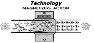
Fig. 3 Magnetizer Action
Furthermore, as the pollutants decrease, the combustion efficiency increases. The drop of HC & CO emissions is easily proven by comparative gas flue analysis & opacimeter emissions tests.
B. Altering the spin properties of the outer shell (“valence”) electron enhances the reactivity of the fuel (and related combustion process). The higher energized spin state of hydrogen molecule clearly shows a high electrical potential (reactivity), which attracts additional oxygen. Combustion engineering teaches that additional oxygenation increases combustion efficiency; therefore, by altering the spin properties of the H2molecule, we can give rise to its magnetic moment and enhance the reactivity of the hydrocarbon fuel and ameliorate the related combustion process. The unit extremely strong magnetic field, with sufficient flux density to have the required affect on fluid passing through it, substantially changes the isomeric form of the hydrocarbon atom from its Para-hydrogen state to the higher energized, more volatile, ortho-state, thus attracting additional oxygen. Fuel structure and properties, such as e.g. electrical conductivity, density, viscosity, or light extinction are changed; its macrostructure beneficially homogenized.
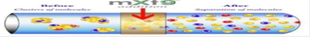
Fig. 4. Schematic view of MFE
C. H2 molecules form clusters called “associations.” It has been technically possible to enhance van der Waal’s discovery due to the application of the Magnetizer, a high power, permanent magnetic device, strong enough to break down, i.e. de-cluster these HC associations. They become normalized & independent, distanced from each other, having bigger surface available for binding (attraction) with more oxygen (better oxidation). A simple analogy is of burning coal dust and a coal brick. Fig 4. Shows schematic view of MFE & Fig5 shows Mechanism of MFE.
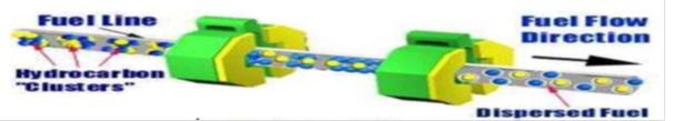
Fig. 5 Mechanism of MFE
Principle of fuel saving
When fuel flows through the Fuel energizer, it magnetizes fuel molecules and puts the molecules temporarily into cationic state. Fuel burning in this state is far more efficient and reduces carbon monoxide emission. Apparatus for the intensified exposure of a hydrocarbon based fuel to a magnetic field comprising at least two permanent magnets having opposite faces polarized north and south, a cover box for containing each of said magnets made from non-magnetic material for containing said magnets and having a bottom opening and a peripheral depending flange having curved hollows for fitting closely about a fluid containment vessel, a backing plate for closing said bottom opening made from non-magnetic material and being recessed inward to permit the close fit of the fluid containment vessel within said curved hollows, and strapping means for securing said cover boxes in fixed diametrically opposed position about said fluid containment vessel for creating an electromagnetic circuit having an enhanced, substantially uniform, mono-directional, magnetic flux density for the polarization of the molecules of said fuel to increase the combustion efficiency of said fuel. The apparatus of said fluid containment vessel is a conduit having a substantially circular cross- section; strapping means for securing the cover boxes in position about the fluid containment vessel are inserted through apertures in each of the cover boxes. The magnetic field effects the polarization of long chain carbon molecules in said fuel so as to unfold said molecules to expose a significantly greater surface area susceptible to combustion. Also it is adapted to be positioned in proximity to an oxygen/fuel mixing apparatus and for utilization in a hydrocarbon based fuel burning engine for the powering of a vehicle and increases the combustion efficiency and reduces environmentally harmful emissions of said engine.
PARAMETER OF MAGNETIC FUEL ENERGIZER
Various parameters which affect the efficiency of fuel combustion are listed below.
- Installation Position: It is just before the carburetor or injector on inlet pipe or housing for maximum alignment & maximum effect.
- Polarity of magnet: Fuel line is magnetized by South Pole and air line is magnetized by North Pole. Such type of opposite polarity burns more completely, producing higher engine output, better fuel economy, and more power and most important reduces the amount of pollutants. The main benefit of such opposite polarity dissolves the carbon built up in carburetor jet, spark plug electrode, injector nozzles and combustion chamber help to clean up the engine parts and maintains the clean condition. Therefore the life of engine parts also increases.
- Diameter of MFE device: Maximum result is being obtained, if diameter is same or close to the system piping.
- Length of MFE device: It will depend upon the volume of fluid to be treated and intensity of treatment. It is generally varied from 12 to 48 cm.
- Magnetic flux: Magnetic flux density which is varies differently on flat surface, core surface. It is observed that maximum effect at center.
- Selection of permanent magnet: The magnet should have a curie temperature sufficiently high that they retained their magnetic characteristic at the operation temperature to which they are exposed. Permanent magnet shows positive result up to its optimum peak, afterwards it will vary.
- Magnetic strength: The strength of magnet depends on engine size. The magnetic flux density to be imparted to fuel widely varies depending upon fuel, air or stream, combustion equipment & its condition. In general the preferred range of Magnetic flux density is from 1000-1800 Gauss. Most preferred range for multicylinder is 1400-1800 Gauss. The field strength is a function of engine size based on fuel consumption .

Fig. 6 Schematic Diagram of Fuel Energizer
INSTALLATON FUEL ENERGIZER
The magnetizing apparatus is located on the pipe between pumping means and the burner, carburetor or fuel injectors, because it is unnecessary for any other parts to be magnetized. A portion of the fuel feeding system extending from a point downstream of the magnetizing apparatus to the burner must be made of non-magnetic material. In this case, magnetized fuel is directly fed to burners or atomizing nozzles with a minimum reduction of magnetism. The magnets are embedded in a body of non-magnetic material, such as plastic, copper or aluminum, to secure them to the fuel line. No cutting of the fuel line and no hose and clamps are necessary to install this device, outside a fuel line without disconnection or modification of the fuel or ignition system for producing magnetic flux in the flow path of combustible fuel within the pipe. These units have been installed without other fuel line or ignition adjustments to treat vehicles failing required emission tests as an inexpensive retrofit accessory to give substantially immediate improvements of up to the order of 80 % reduction in hydrocarbon and carbon monoxide emissions.
In a preferred embodiment, one or more magnets are strapped to the fuel line as close as possible to the carburetor or fuel injectors with only one pole of the magnet or magnets adjacent to or in contact with the fuel line. One or more magnets are strapped to the air intake in such a way as to magnetically expose the oxygen to the magnetic field emanating from the pole opposite that of the pole used to expose the fuel.
Fig. 7 Installation
The magnets should have a Curie temperature sufficiently high that they retain their magnetic characteristics at the operating temperatures to which they are exposed. For example, in an automobile engine, the fuel line magnets will lie above the engine block where relative heating will greatly increase their temperature. Some magnets lose much of their magnetic field strength as their temperature rise. The Curie temperature on Alnico magnet are 760ºC to 890ºC, on Ceramic magnets ( ferrite magnets ) 450ºC, on Neodymium 310ºC to 360ºC and on Samarium 720ºC a 825ºC.
COMPARISON BETWEEN CATALYTIC CONVERTER AND MAGNETIZER
What is a catalytic converter?
A catalytic converter is a vehicle emissions control device which converts toxic byproducts of combustion in the exhaust of an internal combustion engine to less toxic substances by way of catalysedchemical reactions. The specific reactions vary with the type of catalyst installed. Most present-day vehicles that run on gasoline are fitted with a “three-way” converter, so named because it converts the three main pollutants in automobile exhaust: carbon monoxide.
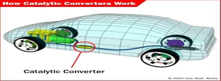
Fig. 8 How Catalytic converter Work
Comparative Study
|
Magnetizer |
Catalytic Converter |
|
| Warranty |
Lifetime |
None |
| Installation |
5 minutes |
45 minutes to 1.5 hour |
| Product Life |
Never wears out |
20 to 50,000 miles |
| Vehicle’s power |
Get Improved |
Less power |
| Vehicle’s Economy |
Get Improved |
Less economy |
| Customer Option |
No |
Poor acceptance |
| Air Pump Required |
No |
Yes |
| Light-off temperature |
No |
Yes |
Table: Comparison (1)
APPLICATIONS OF FUEL ENERGIZER
Use in automobiles
| Buses | Cars | Trucks | Locomotive/Trains |
| Scooter | Ambulance | Earthmoving equipment | Auto rickshaw |
Table: Application in Automobile (2)
Water magnetizer
A simple and effective patented magnetic water conditioner is now available for Swimming Pool, Spa or Hot Tub. By simply strapping the QUANTUM Conditioner on the return line to the Pool, Spa or Hot Tub, laboratory tests prove that the magnetic effect reduces sanitizing chemical usage by 30% to 50% while stabilizing pH, thereby saving money.
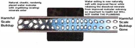
Fig. 9 Water Magnetizer
CONCLUSION
By establishing correct fuel burning parameters through proper magnetic means one can assume that an internal combustion engine is getting maximum energy per liter as well as environment with lowest possible level toxic emission. Magnetic fuel energizer(MFE) increases the internal energy of a fuel to cause specific changes at a molecular level which obtained easier combustion. The resultant fuel burn more completely, producing higher engine output, better fuel economy, more power & most importantly reduces the amount of HC, CO, NOx in the exhaust.& therefore control the emission at low cost. In short the summary of the conclusion includes: MFE increases 10-40% mileage of vehicle, Reduction in HC emission & other pollutants, Avoid clogging problems in Diesel Engine, Cost saving, Eco friendly, Provides 30% extra life for expensive catalytic converter, Reduce maintenance of engine most importantly does not require any design modification & finally cost saving.
REFERENCES
- 1. Shri. N.V. Hargude, Dr. S.M. Sawant,’Experimental investigation of four stroke S.I.Engine using fuel energizer for improved Performance and reduced emissions’ International journal of mechanical Engineering and technology (ijmet), Volume 3, Issue 1, January- April (2012), pp. 244-257.
- 2. Rajan Garg, Ajay Kumar Agarwal,’Fuel Energizer: The Magnetizer (A Concept of Liquid Engineering)’, IJIRD. April, 2013 Vol 2 Issue 4.
- 3. Shweta Jain, Prof. Dr. Suhas Deshmukh,’Experimental Investigation of Magnetic Fuel Conditioner (M.F.C) in I.C. engine’ IOSR Journal of Engineering (IOSRJEN) ISSN: 2250-3021 Volume 2, Issue 7(July 2012), PP 27-31.
- 4. P. Govindasamy and S. Dhandapani,’ Experimental Investigation of Cyclic Variation of Combustion Parameters in Catalytically Activated and Magnetically Energized Two-stroke SI Engine’, Journal of Energy & Environment, Vol. 6, May 2007.
- 5. P. Govindasamy and S. Dhandapani,’Performance and emission achievement by magnetic energizer with a single cylinder with two stroke catalytic coated spark ignition engine’, Journal for scientific research & Engineering, Vol 66 June 2007.
- 6. http://www.magnetizer.com/tech9.html#top , http://www.tinet.cat/~sje/mag_fuel.htm .