Title: MINIMISING THE POWEER THEFTS USING MICRO CONTROLLERS IN SMART METERS
Author: K.Abhinay, M.Chaitanya & K.V Sudheer, 4th Year BTech, Electrical and Electronics Engineering
Guide: Prof. Meeravali, Department of Electrical and Electronics Engineering
College: Prakasam Engineering college, Kandukur
AIM: This project of ours is aimed at reducing the illegal power usage in homes by using micro controller and alarms.
ABSTRACT: The present thesis, Microcontroller Based Power Theft Identifier, introduces the concept of preventing the usage of the electrical power. The technology of Microcontroller is utilized to find out the user trying for pilferage of power i.e, by displaying the respective consumer number and address.
For the complete operation, the system can be sub divided into two major sections, one is the transmission section and other is receiving section has to be placed at the electrical sub-station.
INTRODUCTION: By this design would like to conclude that power theft can be effectively decreases by detecting where the power theft. Also a automatic circuit breakers add to the unit so as to remotely cut off the power supply to the house who tries to use the illegal power. By our project we can inform or send data digitally to the sub- station so a large amount of possibilities to the way the power supply is controlled by the electricity board. We have taken into consideration a large number of possibilities in which the power theft may occur and have designed accordingly to prevent it.
Thus by the above mentioned design we can successfully address the problems related to power theft by the consumer cost effective and most importantly a reliable way.
SOME COMMON METHODS TO IDENTIFY THE POWER THEFT ARE GIVEN BELOW:
There are many methods that assist in power theft identification. Some of them are:-
1. TAMPER PROOF SEALS AND LABELS: A sealing ring assembly for an electric meter including a pair of radially projecting spaced ears having aligned rivet holes through which an elongated rivet is received. The rivet, of substantially hard material, such as case-hardened steel, is held in position by a sleeve, fitted over the free end of the rivet, and a set screw in the sleeve radials bearing against the rivet, the set screw being a shear-headed type in which the head has been sheared off substantially flush with the radial exterior surface of the sleeve.
2. TAMPER RESISTANCE SCREWS/LOCKS: Tamper resistance is resistance to tampering (intentional malfunction) by either the normal users of a product, package, or system or others with physical access to it. There are many reasons for employing tamper resistance.
Tamper resistance ranges from simple features like screws with special heads more complex devices that render themselves inoperable or encrypt all data transmissions between individual chips, or use of materials needing special tools and knowledge. Tamper-resistant devices or features are common on packages to deter package or product tampering.
Anti-tamper devices have one or more components: tamper resistance, tamper detection, tamper response, and tamper evidence. In some applications, devices are only tamper -evident rather than tamper-resistant.
3. TAMPER ALARMS AND SENSORS: Sensors such as movement detectors tilt detectors, air-pressure sensors, light sensors, etc., which might be employed in some burglar alarms, might also be used in a bomb to hinder defusing.
“This paper under takes the check mater and remote meter readers for power theft identification.”
In our case , the consumption recurred by the check meter is compared revenue meter consumption .but the above methods are very common methods to identify the power theft and these are not accurate to find out who are utilizing electricity illegally.
“Meter leaders and check meters and remote readers are also detecting modern tools.”
So in our paper we introduce a new method to find power theft by using microcontroller.
THE BLOCK DIAGRAM REPRESENTATION FOR THE MICROCONTROLLER IS AS REPRESENTED BELOW:
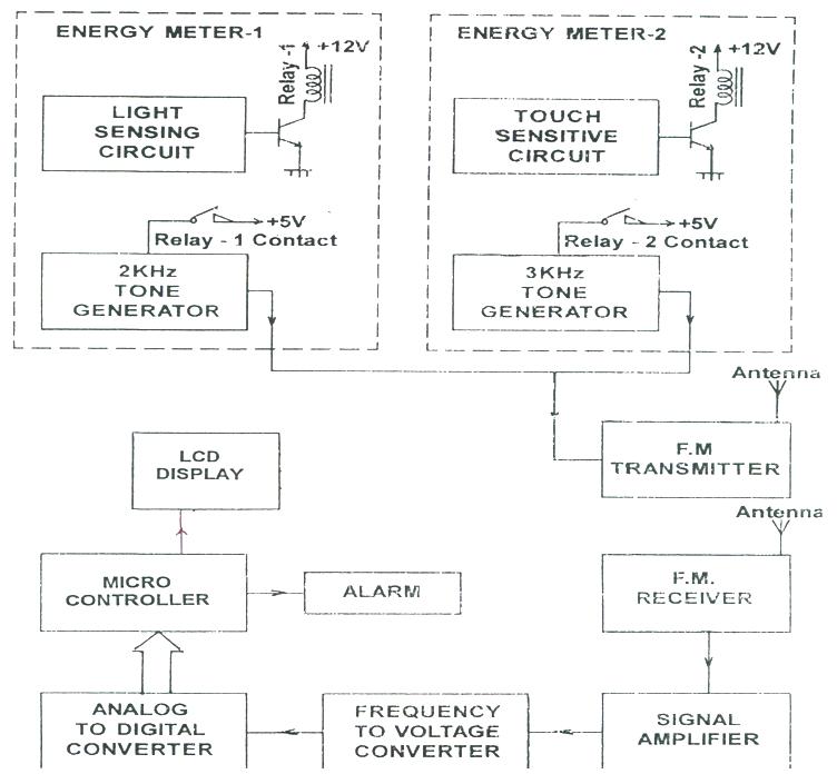
In our paper MICROCONTROLLER BASED POWER THEFT IDENTIFIER is categorized into two sections 1.Energy theft detection unit (transmitter section) located at consumer’s place
2. Display unit using microcontroller (receiver section) located at sub-station.
NEED FOR MICRO CONTROLLER:
A microcontroller (sometimes abbreviated µC, uC or MCU) is a small computer on a single integrated circuit containing a processor core, memory, and programmable input/output peripherals. Microcontrollers are used in automatically controlled products and devices, such as automobile engine control systems, implantable medical devices, remote controls, office machines, appliances, power tools, toys and other embedded systems.
The need of using micro controller arise from the fact that, for a product design which requires only a simple system, the microcontroller identifies all the functions needed to make up a simple microprocessor system and puts as many as possible in a single IC. The microcontroller used in this project consisting IC555 timer,PLL IC CD 4046 and multiplexer CD4053 and FM radio receiver with IC5591A
TRANSMITTER SECTION: The energy theft identification unit is located at energy consumer’s location consists of LDR configured into monostable mode using IC 555 timer. The timer consists of two comparators which are enable at 1/3 Vcc and2/3vcc. Thus as long as the light doesn’t fall on the LDR, the output of the timer is at low state. Whenever the energy meter is opened or tampered the light falls on the LDR. This makes the resistance of the LDR to fall to low value of less than 500 ohms from high value of more than 100K ohms. This is turn changes the threshold level of the timer and the output is high. This will enable relay driving transistor and it turn energizes the relay. This relay in turn provides supply to the tone generator circuit i.e.; the modulating input block.
The audio tone generator is configured with 555 timers IC in astable mode. The frequency of the timer is selected with R-C of circuit. The tone generator generates the tone frequency corresponding to the electric consumer involved in energy theft.

RECEIVER SECTION: The circuit at centralized sub-station consists of F.M radio receiver built with IC 5591A.in this case; it is used as a F.M detector and limiter with minimum of external components. This IC includes cascade stages of IF limiter and balanced product detector with a very low harmonic distortion and high IF voltage gain .the detect signal of the FM receiver is fed to audio amplifier, which amplifies the signal. The amplified signal is fed to frequency to voltage converter that uses phases locked loop IC CD 4046 and multiplexer CD 4053. This frequency to voltage converter circuit converts the input frequency in to output D.C voltage. The phase locked loop IC contains a stable, highly linear voltage controlled oscillator for low distortion F.M demodulation, and double balanced phase detection. the characteristics of the closed loop system , band width , response , speed , capture and pull in range may be adjust over a wide range with external resistors and capacitors . There by D.C output voltage, which is proportional to the tone frequency, is fed to the analog to digital converter block.
This process can be done by using above block diagram is whenever the consumer try to get the power theft in meters the transmission section which is placed in the smart meters, it sends the signal to the receiver section which is placed at the sub-station, whenever the receiver receives the signal it displays the meter number.
MERITS:
• By this system very little power is consumed for its operation.
• System operation is not time dependent (24hr function).
• Automatic users’ identification.
LIMITATIONS:
• In this method use the simple electronics, the change of king the system inoperative are more. But if a Microcontroller chip is used for feeding the modulation input, we can make the system more efficiently.
• Wide range of frequencies is required to facilitate large number of users. To overcome this, carrier levels can be changed from region to region.
• Practically it requires a power supply (230 V) for the operation, but a small battery with automatic charging facility can be provided in real time.
APPLICATIONS:
• The system can be incorporated for almost all type of users.
• This concept is well suited especially for villages and interior areas.
• It can be implemented at highly populated areas.
CONCLUSION:
In this present project, the scheme for indicating the power theft is based on the concepts of micro controller. By using this technology we can distribute more efficiently. By clear study of our project we almost reduce the power theft, which is used to distribute power without any losses. But, when the system has to be employed in real time, a lot of sophisticated schemes can combinely be employed so that the chances for power theft can almost be eliminated. The concept can be applied to places where proper measure and preventive steps cannot be easily taken, especially for villages and interiors areas. The present system has to undergo lot of modifications and sufficient R & D has to be done to make the system more compact, handy and economical. With the implementation of this kind of systems in the real time, the need for regular vigilance can be avoided and power can be supplied at the economical rates, thereby improving the economy of the country.
REFERENCES:
http://www.picotech.com/experiments/calculating_heart_rate/
http://www.mytutorialcafe.com/Microcontroller%20Project%20Thesis%20RTC%204051.htm
http://www.bioenabletech.com/gsm_gprs_gps_mobile_m2m_india.htm