Title: Modified Water Coolers
Author: Sourav S Sen, 4th Year, Mechanical Engineering
Guide: Asso Professor. N K Patil
College: SSBT’s College of Engineering and Technology, Bambhori, Jalgaon
ABSTRACT-
This paper comprises of a solution to increase the efficiency of water coolers by using the same water which is wasted in drainage. Water that is allowed to drain directly can be used effectively to increase the efficiency of the system to good extent. Water which is normally used for washing glasses or sometimes is let to flow from the taps is chilled. Passing this chilled water on the cool water reservoir and on condenser tubes will increase the efficiency of system. Water coolers working on simple refrigeration cycle are taken under consideration in this paper however this is a solution which can be applied to any water coolers .Either refrigerant or directly water if used for cooling this system can be implied on any of them.
INTRODUCTION-
Water coolers in India are used almost in every school, industry, business and restaurants on a regular basis and run nearly about 18 hours a day in the summer season and 2- 3 hours also. Increasing the efficiency of these water coolers can significantly decrease the power consumption of the water coolers as a result adding to the overall profit of the company.
The solution to this is by simple recycling the cold water that is let through drainage towards the cool water chamber and passing the condenser coils through this .This in return will increase the cooling capacity of the coils an after evaporation of refrigerant it can be taken to a much less temperature, saving considerable amount of electricity and providing a better cooling effect.. In this setup we will use evaporative type cooling for the condenser tubes after the air cooling of the tubes. As a result the refrigerant in the condenser tubes will reach lower temperatures at a specified pressure ratio faster also as air cooling is much slower than water cooling. This will not only decrease the amount of refrigerant to provide the cooling effect but it will also speed up the process. As a result the overall size of the water cooler will decrease but it will be able to cool much more amount of water than before.
WORKING OF A SIMPLE WATER COOLER
A basic water cooling system contains the following parts
1. Evaporator
2. Compressor
3. Condenser
4. Expansion valve
Fig 1.1 Schematic diagram of a basic Vapour Compression System

The above fig 1.1 shows the basic vapor compression refrigeration system .In this evaporator consists of the part of the refrigerator from where the heat is to be taken off. The compressor compresses the vapor and takes it to superheated state. The evaporator in which we are going to make changes is cooled by air in simple water coolers. Then primary refrigerant is passed through the expansion valves, where the expansion creates very low temperature from which it can absorb the heat from the system which is required to be cooled.

Fig 1.2 Vapor Compression system
Figure 1.2 shows us a simple vapor absorption system in which the compressor compresses the liquid from 1 to 2 but as the compression is not totally isentropic so it goes to 2’. Then it moves to the condenser from 2’ to 4 in the condenser tubes. Here the refrigerant loses its heat to the atmosphere and after that it is passed on to the expansion valves. After expansion it goes to 5’.then the cooling load is taken by the evaporator.
MODIFIED WATER COOLER
In this an addition of extra evaporator segment will be there. In this evaporator water that has been spilt or used for washing of glasses or leaked from the tap is taken and is used to fill the evaporator tank. The condenser tubes are passed through this evaporator tank which will in turn cool the condenser refrigerant as a result the water will evaporate by taking its latent hear of evaporation and leaving the refrigerant at a much cooler state than before.When the liquid will be hot enough a temp sensor can sense it and let go of the water from the bottom using a small opening at the end. When water will not be there in the chamber the condenser tubes again will get cooled by the air as it used to do before.
Fig1.3
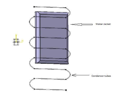
The above figure shows us the schematic diagram of the condenser tubes passing from the water jacket .The above figure is accomplished by the use of CATIA v5
CALCULATIONS
Basic equations required for calculations are as follows :
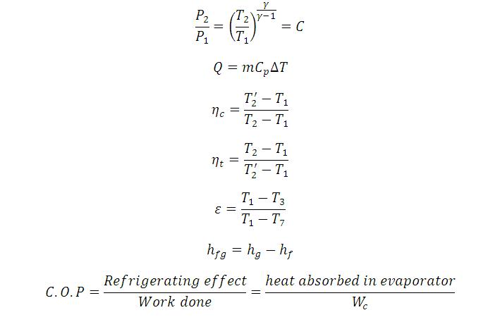
Here P2 = final pressure, T2 = final temp after compression,
P1= initial pressure, T1= initial temp,
ηc = Compressor efficiency ηT= Turbine efficiency ε= Effectiveness of heat exchanger
T3=Temp of the refrigerant coming out of the heat exchanger,
T7=Temp of water used to cool the refrigerant,
P2/P1= Compression ratio,
hg=enthalpy of gas hf=enthalpy of fluid
Wc=Work done by the compressor,
C=Compression Ratio
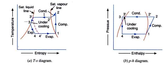
Fig1.4 Sub-cooling in the modified watercooler
Undercooling in a basic vapor compression cycle generally increases the C.O.P of a vapor compression cycle [2]. This undercooling will increase the refrigerating effect from h4’-h1 to h4-h1. Hence the chilled water which is at temp below T3 can be used to cool the refrigerant to a substantial value otherwise when there is no water in the jacket it will be simply air cooled again. Assume that the effectiveness of heat exchanger is ε.
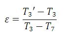
So even if the effectiveness is less than 20% which off course will be more than it then it will increase the efficiency of total system. Now
Now if we increase the change in temp term in the above equation we get overall increase in the refrigerating effect.
As compression work remains the same the C.O.P increases.
Conclusion
The overall efficiency of a water cooler is increased by easily just recirculating the waste water from the watercoolers. This not only just accelerates the process but also sub-cools it to a certain limit than the normal air cooling due to the temp difference between the chilled water released from taps and the compressed refrigerants.
REFERENCES
[1] J K Gupta and R S Khurmi, : A textbook of refrigeration and air conditioning, 126 p.
[2] Stoecker & Jones: Refrigeration & Air Conditioning 40 p.
[3] Watt J.R. 1986. Evaporative air conditioning handbook. Chapman and Hall, London.