Technical Paper Title: Power-System Frequency and Stability Control using Decentralized Intelligent Loads
Authors: V.Suneetha & A.Shobarani, 3rd BTech, EEE
College: Prakasam Engineering College, Kandukur
ABSTRACT:
Modern power systems operate on the premise that the load is uncontrollable and that system voltage, frequency and stability are primarily maintained through control of the generation. In this paper, we challenge this premise by proposing a much more active role for intelligent loads specifically related to frequency control and dynamic stability. In modern systems the load is typically only controlled under severe stability conditions via load shedding. That the many loads could cost-effectively become intelligent, allowing for the potential of the loads to more actively participate in system operation and control. The potential benefits of active load control are investigated. Also, reliability and implementation issues are explored. Fundamental analysis and multi-machine system simulation examples are used to demonstrate many of the issues.
INTRODUCTION:
Majority of interconnected power systems operate on the premise that the load is uncontrollable. System voltage, frequency and stability are primarily maintained through the real-time control of the generation. For example, system frequency is controlled through adjustment of the mechanical power of the generators using speed governor feedback and area generation control (AGC) .Similarly, dynamic stability enhancement is conducted through adjustment of the generator’s excitation voltage via the power system stabilizer (PSS) loop, and more recently, transmission level FACTS devices. Typically, the load is only controlled under severe stability conditions such as under-frequency load shedding. Traditional system operators view the load as a variable uncontrolled demand, and the generation must constantly adjust to reliably meet the demand. In this way, “Eighty-five years of regulatory efforts have focused exclusively on supply – leaving on dusty shelves proposals to empower consumer demand, to help stabilize electric systems while creating a more flexible economic environment.”
The primary goal of which is to develop intelligent resources that can improve transmission and distribution reliability, efficiency and security.
The goal of this paper is to examine the potential of the intelligent load technologies for improving power system frequency and stability control and to identify the challenges that must be overcome to meet this potential.
II. EXAMPLE TEST SYSTEM:
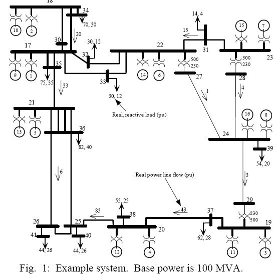
To examine load control issues, the example simulation test system shown in Fig. 1 is employed. The system consists of major generation buses 17 thru 24. Each generation bus has two generators connected to it; one generator is a fixed-power unit with a constant mechanical power and no speed-governor control (generators 1 thru 8); the other generator is equipped with a traditional speed governor (generators 9 thru 16). Generators 9, 10, 14, and 16 are driven by hydro turbines and generators 11, 12, 13, and 15 are driven by faster acting steam turbines. All generators are equipped with fast-acting voltage regulators and PSS units, and all are modeled using a detailed two-axis transient model.
The test system has loads connected to buses 31 thru 41 disbursed throughout the system. Each load can be split into a portion consisting of constant impedance, constant current, constant power, and controllable. The baseline line-flows and loads are shown in Fig. 1
III. LOAD FREQUENCY CONTROL STRATEGY
A simple and arguably optimal control strategy is to linearly modulate load based on frequency error. This will provide a damping torque to electromechanical dynamics and provide improved frequency regulations.
To demonstrate this, consider the traditional swing equation for a given generator where H is the generator’s per unit inertia constant, ω is the per unit speed, Pmech is the mechanical power from a turbine, and Pelec is the generator’s electrical output power. Because ω is relatively constant, examination of (1) with modulation of Pelec based on speed error results in a damping torque. Also, the larger the modulation, the higher the damping torque. This is a well-established concept and is the fundamental basis for modern power system stabilizer (PSS) design.
In the electromechanical frequency range, the generator’s output power (Pelec) is algebraically related to the loads at each bus. We hypothesize that modulation of the load’s real power based on the frequency error at the bus results in the appropriate modulation of Pelec at each generator. We demonstrate the potential with the following simulation examples.
A. Example 1: Control vs. no control
For this simulation example, the system is initially operated at the baseline loading condition. Each fixed-power generator is loaded to 50% of the power produced at that bus. For example, generator 1 produces 50% of the power injected into bus 17, while generator 9 produces the other 50%.
For the controlled case that follows, the real power at each load bus is modulated using the control law
∆Pk=Kp*∆fk_____________(2)
where
k = bus number (31 thru 41),
Δfk = electrical frequency error in Hz at bus k,
ΔPk = power modulation at bus k in percent of baseline loading at bus k,
Kp = control gain in units percent/Hz.
The unit of measurement for ΔPk is percent of baseline loading; that is, if ΔPk = 1, then 1% of the load is modulated. For the simulation in this example, Kp = 100 and the absolute maximum ΔPk allowed at each bus is +20%. Therefore, if the frequency drops to 59.8 Hz, the load will be modulated by 20%.
The simulation consists for two step changes in the load at each load bus to bring the system from the baseline loaded condition to a more heavily loaded condition. The switching actions in terms of time (t) are:
t = 1 sec. – all real and reactive loads are suddenly increased by 5% of the baseline loading;
t = 40 sec. – all real and reactive loads are suddenly increased by 15% of the baseline loading;
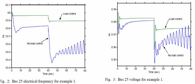
The loads are changed using a stepping function to accentuate the effects of the load control. In reality, the loads would slowly change over the course of a day, but the step changes demonstrate the controller performance with a small simulation time. Fig. 2 shows the electrical frequency at bus 25, Fig. 3 shows the voltage at bus 25, and Figs. 4 and 5 show the power flowing from bus 20 to 25 for the simulation.
For the no-control case, the slow-moving portion of the response is caused by the speed governor’s attempt to maintain frequency. The frequency does not fully recover after the increased loading because of the droop effect in the speed-governor control. Eventually, the AGC system would increase the swing generators’ output to fully recover frequency (typically, this requires several minutes). The higher frequency swings in the no-control case are caused by electromechanical oscillations. As is typical for a stability-limited power system, the oscillations become undamped at the heavier loading indicating unacceptable unstable operation.
As seen in Figs. 2 thru 5, the load control considerably improves the frequency regulation and stability of the system. Without load control, the second increase in load causes the heavily loaded system to go into an undamped oscillation. With load control, the system is much more stable and has nearly no oscillations and improved voltage regulation. Also, the frequency regulation with load control is much faster and accurate in the steady state. The required power modulation for the results shown in Figs. 2 thru 5 is approximately 11% of the baseline.
With the load control, the transmission system reliably operates at a higher loading level without stability issues
IV. REDUCED SPEED GOVERNORS:
As shown in the previous example, load control can significantly contribute to the system’s frequency regulation. One advantage of this is that fewer generators would require speed governor control, allowing for increased fixed-power loading. This may be of considerable interest to power producers because many power plants operate more efficiently under fixed-power loading. The extent of frequency regulation available from load control is certainly system dependent, but, as the following example demonstrates, the potential is significant.
A. Example 2: Speed Governors vs. No Speed Governors
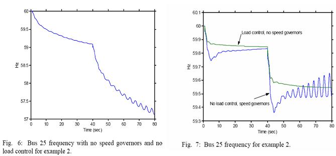
First simulate the system’s response with all generators’ fixed-power loaded (i.e., no speed governors are employed and all mechanical powers are set to a constant) and no load control. Fig. 6 shows the system’s response to the same disturbances as used in example 1. As expected, the frequency is unstable and diverging because there is a mismatch in generation and load. If speed governors are used on 50% of the generators, the system’s frequency recovers, as shown in the “no control” case in Fig. 2 of example 1 (bus is still unstable). Our goal is to determine the magnitude of load control required to match the 50% speed-governor response using load control and all fixed-power turbines.
The simulation is repeated with load control, with Kp = 25 and the absolute maximum ΔPk allowed at each bus is 20%. The results are shown in Fig. 7. As can be seen, the load control provides similar frequency regulation as the speed governor control. The dynamic stability response of the load control case is stable and has considerable damping. One can improve the regulation by increasing Kp.
V. IMPROVED POWER TRANSFER:
For stability-limited systems, improving the dynamic stability of the system provides the opportunity to transfer more power over the same transmissions system. The extent of increase is highly system dependent, but with load control, the potential can be significant. This is demonstrated in the following example.
A. Example 3: Improved Power Transfer
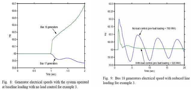
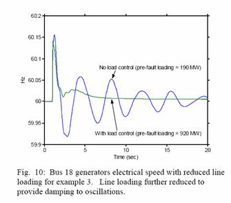
Consider the transmission system from bus 18 to 17 in Fig. 1. To maintain reliability, we require that the system must return to a stable condition following a three-phase three-cycle fault on one of the parallel lines between the buses. For the baseline loading case and no load control, the results are shown in Fig. 8. As seen in the figure, the system is transient unstable with generators connected to bus 18 losing synchronism with the rest of the system.
The traditional power-planning approach for solving the unstable problem is to reduce the pre-fault line loadings of 2000 MW until a stable response is achieved and then operate the system such that this safe loading level is never exceeded. This is done by adjusting the mechanical power set points of generators 2 and 10. With no load control, the pre-disturbance line loading must be reduced to 780 MW to achieve a marginally stable response. If load control is employed using the same control parameters as example 1, a stable response is achieved at a line loading of 920 MW. Therefore, the load control enables a 18% increase in line loadings.
The system’s responses to these two new conditions are shown in Fig. 9. Under both cases, generators connected to bus 18 returns to synchronism; but, without load control, the system has a very low frequency lightly-damped electromechanical oscillation indicating the system is still near an unstable condition. With load control, the system has no noticeable oscillations. The no-control oscillations unacceptable and would further decrease the pre-fault loading. As an example, one may have the requirement that the oscillations must be significantly decayed within 20 seconds. To achieve this, the no-control pre-fault loading must be decreased to at least 190 MW; the results from this case are shown in Fig. 10. When compared to the 920 MW loading achieved with load control, the load modulation enables a 380% increase in loading.
One must be cautious not to generalize the results in this example to other systems. All stability-limited cases are unique; but, the example does demonstrate the potential of the concept. Loads within the southern California portion of a detailed model of the western North American power system are modulated by +450 MW. The modulation dampens north-south system oscillations and enables an additional 400 MW of power transfer on a critical transmission path.
VII. BENEFITS, CHALLENGES, AND CONCLUSIONS
The results and discussions presented here open the door to many specific questions and challenges.
BENEFITS:
Certainly, load control offers considerable potential benefits, including:
- • Improved system stability, and therefore, a more cost-effective transmission system;
- • Improved frequency regulation that may allow more generators to be operated under baseline loading, and therefore, more efficient power plant operation.
These benefits could likely result in significant cost savings to the electric energy industry. Assuming, that controllable loads can be developed.
Challenges:
. Challenges related to frequency regulation and dynamic stability include:
- • Will the control law always provide improved stability and frequency regulations for all power systems? Is this the best control strategy?
- • How closely and reliably can the control law in be implemented using a highly distributed control action down to the consumer level? Related to this: Can frequency error be accurately measured at the distribution level where load “noise” effects can be significant?
- • Can load control participate in AGC? Will this require expanding the control law to include communication with the AGC? Answering these questions will certainly require significant research. Also, the results of specific study cases will provide critical information on the cost-benefit analysis.
CONCLUSION:
In this paper we conclude that the potential of the intelligent load technologies for improving power system frequency and stability control. From examining the potential, the generation and transmission benefits that could be obtained from load control are identified. The specific technology challenges related to intelligent load control are hypothesized. Answering some questions will certainly require significant research. Also, the results of specific study cases will provide critical information on the cost-benefit analysis.

