Technical Paper Title: WIRELESS POWER TRANSMISSION
Authors: Y. PARVATHI & M. SRAVANTHI , 1st BTech, EEE
Guide: Prof. Meeravali
College: Prakasam Engineering College, Kandukur
ABSTRACT:
Transmission or distribution of 5o Hz or 60 Hz electrical energy from the generating point to the consumers’ end without any physical wire has yet to as a familiar and viable technology.
This paper focuses on the past and future possible advancements in WPT and explaining why it has still not come into practical utility.
Wireless energy transfer has been around for about a century, but as of yet has only found usage in things like electric toothbrush rechargers and specialty applications such as beaming solar power down from space.
A simple demonstration of it can be constructed at home with ordinary materials. A loop of wire short circuiting a battery will cause a compass needle placed near it to point, and by tapping one end of the wire on and off of its electrode you can cause the needle to twitch. The transverse magnetic field induced in the line acts on the compass, performing work without the use of a physical connection.-
History:
As the wireless art developed during the turn of the 20th century, industry was looking toward a method of wireless energy transfer. Some of the then scientists are
Hertz: A precursor of this technology can be found in the works of Heinrich Rudolf Hertz in the late nineteenth century. In 1888, Hertz experimented with pulsed power transmission at 500 megahertz.
Tesla: Tesla was able to light gas discharge lamps, he lit ordinary incandescent lamps at full candle-power by currents induced in a local loop consisting of a single wire forming a square of fifty feet each side, which includes the lamps, and which was at a distance of one-hundred feet from the primary circuit energized by the oscillator.
Yagi: In Japan, Hidetsugu Yagi attempted wireless power transmission. In February 1926. Yagi managed to demonstrate a proof of concept, but the engineering problems proved to be more onerous than conventional systems.
The Need for a Wireless System of Energy Transmission:
A great concern has been voiced in recent years over the extensive use of energy, the limited supply of resources, and the pollution of
the environment from the use of present energy conversion systems.
Electrical power accounts for much of the energy consumed. Much of this
power is wasted during transmission from power plant generators to the
consumer. The resistance of the wire used in the electrical grid
distribution system causes a loss of 26-30% of the energy generated.
This loss implies that our present system of electrical distribution is
only 70-74% efficient.
A system of power distribution with little or no loss would conserve
energy. It would reduce pollution and expenses resulting from the need
to generate power to overcome and compensate for losses in the present
grid system.
The proposed project would demonstrate a method of energy
distribution calculated to be 90-94% efficient. An electrical distribution system, based on this method would eliminate the need for an inefficient, costly, and capital intensive grid of cables, towers, and substations. The system would reduce the cost of electrical energy used by the consumer and rid the landscape of wires, cables, and transmission towers. The greatest amount of power used, the peak demand, is during the day. The extra power
available during the night could be sold to the side of the planet
where it is day time. Considering the huge capacity of power plants in
the United States, this system would provide a saleable product which
could do much to aid.
Methods for wireless energy transfer:
There are three main methods for wireless energy transfer in use today; induction, electromagnetic transmission (power beaming), and evanescent wave coupling.
Induction
Transformers are probably the simplest example of wireless power transfer. The two circuits of a transformer are physically isolated, but transfer (and transform) power by magnetic coupling through induction. Induction cookers are a prime example of how this is used. In an induction cooker, energy is transferred directly and wirelessly into the pot or pan, where it is converted ohmically into heat for cooking. The main drawback to induction, however, is the short range. The receiver must be very close (nearly direct contact) to the inductor unit in order to magnetically couple with it.
Electromagnetic transmission:
Electromagnetic waves, commonly known as light, can also be used to transfer power wirelessly. By converting electricity into light, such as a laser beam, then firing this beam at a receiving target, such as a solar cell on a small aircraft, power can be beamed to a single target. This is generally known as “power beaming”. There are several drawbacks to this, however. First, the conversion to light, such as a laser, is usually very inefficient. Also, atmospheric absorption causes further losses. Finally, this method requires a direct line of sight with the target, and is unsuitable for transmitting too many targets or over a broad area.
Evanescent wave coupling:
Researchers at MIT believe they have discovered a new way to wirelessly transfer power using non-radiative electromagnetic energy resonant tunneling. Since the electromagnetic waves would tunnel, they would not propagate through the air to be absorbed or wasted, and would not disrupt electronic devices or cause physical injury like microwave or radio transmission. Researchers anticipate up to 5 meters of range.
The first model:
William C. Brown, the leading authority on wireless power transmission technology, has loaned this demonstration unit to the Texas Space Grant Consortium to show how power can be transferred through free space by microwaves. A block diagram of the demonstration components is shown below. The primary components include a microwave source, a transmitting antenna, and a receiving rectenna.
The microwave source consists of a microwave oven magnetron with electronics to control the output power. The output microwave power ranges from 50 W to 200 W at 2.45 GHz. A coaxial cable connects the output of the microwave source to a coax-to-waveguide adapter. This adapter is connected to a waveguide ferrite circulator which protects the microwave source from reflected power.
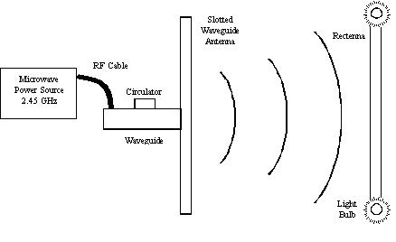
The circulator is connected to a tuning waveguide section to match the waveguide impedance to the antenna input impedance.
The slotted waveguide antenna consists of 8 waveguide sections with 8 slots on each section. These 64 slots radiate the power uniformly through free space to the rectenna. The slotted waveguide antenna is ideal for power transmission because of its high aperture efficiency (> 95%) and high power handling capability.
A rectifying antenna called a rectenna receives the transmitted power and converts the microwave power to direct current (DC) power. This demonstration rectenna consists of 6 rows of dipoles antennas where 8 dipoles belong to each row. Each row is connected to a rectifying circuit which consists of low pass filters and a rectifier. The rectifier is a GaAs Schottky barrier diode that is impedance matched to the dipoles by a low pass filter. The 6 rectifying diodes are connected to light bulbs for indicating that the power is received.
The light bulbs also dissipated the received power. This rectenna has a 25% collection and conversion efficiency, but rectennas have been tested with greater than 90% efficiency at 2.45 GHz.
Project Tesla:
The Wireless Transmission of Electrical Energy Using Schumann Resonance.
It has been proven that electrical energy can be propagated around
the world between the surface of the Earth and the ionosphere at
extreme low frequencies in what is known as the Schumann Cavity. The
Schumann cavity surrounds the Earth between ground level and extends
upward to a maximum 80 kilometers. Experiments to date have shown that
electromagnetic waves of extreme low frequencies in the range of 8 Hz,
the fundamental Schumann Resonance frequency, propagate with little
attenuation around the planet within the Schumann Cavity.
Knowing that a resonant cavity can be excited and that power can be
delivered to that cavity similar to the methods used in microwave ovens
for home use, it should be possible to resonate and deliver power via
the Schumann Cavity to any point on Earth. This will result in
practical wireless transmission of electrical power.
Range and rate of coupling
The range and rate of the proposed wireless energy-transfer scheme are the first subjects
Of examination, without considering yet energy drainage from the system for use into work. An appropriate analytical framework for modeling this resonant energy-exchange is that of
“coupled-mode theory” [6]. In this picture, the field of the system of two resonant objects 1 and
2 is approximated by F(r, t).a1 (t) F1(r) +a2 (t) F2(r), where F1, 2(r) are the eigenmodes of 1 and 2
Alone, and then the field amplitudes a1 (t) and a2 (t) can be shown to satisfy, to lowest order:
da/dt = –I (w-it) + ik
Influence of extraneous objects
Clearly, the success of the proposed resonance-based wireless energy-transfer scheme depends strongly on the robustness of the objects’ resonances. Therefore, their sensitivity to the near presence of random non-resonant extraneous objects is another aspect of the proposed Scheme that requires analysis. The appropriate analytical model now is that of “perturbation theory”, which suggests that in the presence of an extraneous object e the field amplitude a1 (t) inside the resonant object 1 satisfies, to first order:
Efficiency of energy-transfer scheme
Consider again the combined system of a resonant source s and device d in the presence of a set of extraneous objects e, and let us now study the efficiency of this resonance-based
Energy-transfer scheme, when energy is being drained from the device at rate work à for use into operational work.
Market analysis
More efficient energy distribu-tion systems and sources are needed by both developed and under developed nations. In regards to Project Tesla, the market for wireless power transmission
systems is enormous. It has the potential to become a multi-billion dollar per year market.
Some practical applications are shown below with their respective diagrams:
(1)
• The above picture was the first demonstration of the wireless energy propagation
(2)
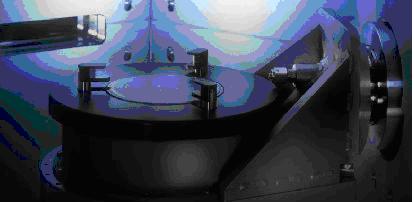
• This picture is the first experimental project of Tesla. It proved the possibilities
(3)
(4)
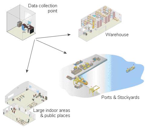
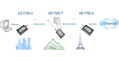
• This technique can be in very effectively used in data transfer between the intranet service providers.
(5)
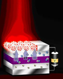
• The above figure shows the infrared display of the material emitting some energy when supplied to a battery. The charge recombination obviously explains the wireless transfer of energy.
Market Size:
If a conservative assumption was made that the three-quarters of the world
which is only using one-quarter of the current power production were to
eventually consume as much as the first quarter, then an additional 908
million kilowatts will be needed. The demand for electrical power will
continue to increase with the industrialization of the world.
EnvironmentalConsiderations:
The extreme low frequencies (ELF), present in the environment have
several origins. The time varying magnetic fields produced as a result
of solar and lunar influences on ionospheric currents are on the order
of 30 nanoteslas. The largest time varying fields are those generated
by solar activity and thunderstorms. The magnetic flux densities associated with these resonant frequencies vary from 0.25 to 3.6 picoteslas. Per root hertz
(pT/Hz1/2). Exposure to man made sources of ELF can be up to 1 billion (1000 million or 1 x 10⁹) times stronger than that of naturally occurring
fields. ELF antennae systems that are used for submarine communication produce fields of 20 uT. Video display
terminals produce fields of 2 uT, 1,000,000 times the strength of the
Schumann Resonance frequencies.9
Calculations predict that the field strength due to this
excitation at 7.8 Hz will be on the order of 46 picoteslas.
Advantages:
(1) Wireless energy transfer can potentially recharge laptops, cell phones without chords.
(2) No need of the wires to transfer the electricity.
(3) Although, the energy is different, the appliances use a very little amount.
Disadvantages:
(1) The transmitter and receiver also should be very powerful devices as the distance increases.
(2) Wireless transmission of the energy causes some drastic effects to human body, because of its radiation.
(3) Practical possibilities are not yet applicable as there is no much advancement in this field.
(4) Initially, the procedure will be very expensive.
(5) All the present appliances can’t be attached with a transmitter and receiver.
Uses: The wireless transfer of energy is used in various devices, such as electric toothbrushes (to recharge their batteries), the transcutaneous energy transfer (TET) systems in artificial hearts like AbioCor and most notably in mobile phones.
Future vision:
A fully developed World System would, conceivably, allow for the removal of many existing high-tension power transmission lines, and facilitate the interconnection of electrical generation plants on a global scale.
Conclusion:
What we wanted to explain in this paper is that the wireless trans-mission of the energy can be converted to electricity and then can be used for many many appliances If this technology develops much faster, we can soon see the radiated world; we mean the energy can be harnessed from any location of the earth.
Let us work and wait for the day and we soon see the electrical revolution drastically changing.


