Title: A Study Paper on Jet Engine
Authors: Himanshu Singh, Himanshu Somvanshi & Santosh Shinde, 3rd year, Mechanical Engineering
College: K.K.Wagh Institute of Engineering Education & Research, Nasik
ABSTRACT
This Paper deals with a brief article about a jet engine and its working explained along with its various types. A Jet Engine is a reaction Engine that discharges a fast moving jet which generates thrust by jet propulsion in accordance with Newton’s Law of Motion.
In common parlance, the term jet engine loosely refers to an internal combustion air breathing jet engine (a duct engine). These typically consist of an engine with a rotary (rotating) air compressor powered by a turbine (“Brayton Cycle”), with the leftover power providing thrust via a propelling nozzle. A young German physicist, Hans von Ohain, worked for Ernst Heinkel, specializing in advanced engines, to develop the world’s first jet plane, the experimental Heinkel. He 178. It first flew on August 27, 1939.
Types
Turbine powered
Gas Turbine is rotary engines that extract energy from a flow of combustion gas. They have an upstream compressor coupled to a downstream turbine with a combustion chamber in-between.
Turbojet engine

Turbojet engine
A turbojet engine is a gas turbine engine that works by compressing air with an inlet and a compressor (axial, centrifugal or both), mixing fuel with the compressed air, burning the mixture in the combustor and then passing the hot, high pressure air through a turbine and a nozzle. The compressor is powered by the turbine, which extracts energy from the expanding gas passing through it.
Turbofan
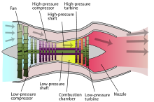
Diagram illustrating the operation of a low-bypass turbofan engine.
Like a turbojet, it uses the gas generator core (compressor, combustor, and turbine) to convert internal energy in fuel to kinetic energy in the exhaust. Turbofans differ from turbojets in that they have an additional component, a fan. The bypassed flow is at lower velocities, but a higher mass, making thrust produced by the fan more efficient than thrust produced by the core.
Ramjet
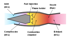
Ram powered jet engines are air breathing engines similar to gas turbine engines and they both follow the Brayton Cycle. Gas turbine and ram powered engines differ, however, in how they compress the incoming airflow. Whereas gas turbine engines use axial or centrifugal compressors to compress incoming air, ram engines rely only on air compressed through the inlet or diffuser.
ROCKET
The rocket engine uses the same basic physical principles as the jet engine for propulsion via thrust, but is distinct in that it does not require atmospheric air to provide oxygen; the rocket carries all components of the reaction mass. Rocket engines are used for high altitude flights as they have a lack of reliance on atmospheric oxygen
An approximate equation for the net thrust of a rocket engine is:
![]()
Where FN the net thrust, specific imoulse is is a standard gravity, m is the propellant flow in kg/s, Ae is the cross-sectional area at the exit of the exhaust nozzle, and p is the atmospheric pressure.
Consumption of fuel or propellant
A closely related (but different) concept to energy efficiency is the rate of consumption of propellant mass. Propellant consumption in jet engines is measured by Specific Fuel Consumption, Specific impulse. Effective Exhaust Velocity. They all measure the same thing. Specific impulse and effective exhaust velocity are strictly proportional, whereas specific fuel consumption is inversely proportional to the others.
For air breathing engines such as turbojets energy efficiency and propellant (fuel) efficiency are much the same thing, since the propellant is a fuel and the source of energy. In rocketry, the propellant is also the exhaust, and this means that a high energy propellant gives better propellant efficiency but can in some cases actually can give lower energy efficiency.
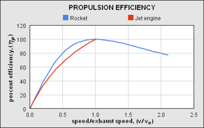
Dependence of propulsion efficiency (η) upon the vehicle speed/exhaust velocity ratio (v/ve) for air-breathing jet and rocket engines.
The energy efficiency (η) of jet engines installed in vehicles has two main components:
Propulsive efficiency (ηp): how much of the energy of the jet ends up in the vehicle body rather than being carried away as kinetic energy of the jet.
Cycle efficiency (ηve): how efficiently the engine can accelerate the jet
Even though overall energy efficiency η is simply:
![]()
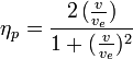
For all jet engines the propulsive efficiency is highest when the engine emits an exhaust jet at a velocity that is the same as, or nearly the same as, the vehicle speed as this gives the smallest residual kinetic energy. The exact formula for air-breathing engines moving at speed v with an exhaust velocity ve is given in the literature as.
![]()
And for a rocket.
In addition to propulsive efficiency, another factor is cycle efficiency; essentially a jet engine is typically a form of heat engine. Heat engine efficiency is determined by the ratio of temperatures reached in the engine to that exhausted at the nozzle, which in turn is limited by the overall pressure ratio that can be achieved. Cycle efficiency is highest in rocket engines (~60+ %), as they can achieve extremely high combustion temperatures and can have very large, energy efficient nozzles. Cycle efficiency in turbojet and similar is nearer to 30%, the practical combustion temperatures and nozzle efficiencies are much lower.
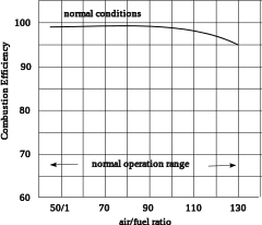
Typical combustion efficiency of an aircraft gas turbine over the operational range.
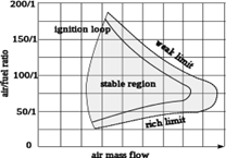
Typical combustion stability limits of an aircraft gas turbine.
The combustion efficiency of most aircraft gas turbine engines at sea-level takeoff conditions is almost 100%. It decreases nonlinear to 98% at altitude cruise conditions. Air-fuel ratio ranges from 50:1 to 130:1. For any type of combustion chamber there is a rich and weak limit to the air-fuel ratio, beyond which the flame is extinguished. The range of air-fuel ratio between the rich and weak limits is reduced with an increase of air velocity. If the increasing air mass flow reduces the fuel ratio below certain value, flame extinction occurs.
In aircraft turbines, the regular fuel ratio is less than the most efficient fuel ratio of 15%. Therefore, only a part of the air is being used in the combustion process. Part of the fuel isn’t completely burned, leaving a mix of carbon monoxide, soot, and hydrocarbon behind. At idle these amount to 50-2000 ppm, and decreases during cruising to 1-50 ppm. That is why the air around airports is bad.
Starting sequence
Argus pulsejet engine was started with acetylene because of the gas’s high flammability in colder weather. It was then switched over to its liquid fuel and Allowed to run for a few moments before the rockets were fired. The rockets
were only used to accelerate the V-1 to take-off speed within the short run allowed by the take-off ramp.
Valves
One of the main parts in a pulsejet engine are the valves, and in the Argus pulsejet the solution is perfect. Airflow meets the valves in an angle of approx. 30 degrees. And when it starts to open up, the angle decrease from 30 to somewhere around 10. Our flower shape valves are different. Airflow meets the valves at 90 degrees and when these are fully open the angle is approx. 75 degrees. This is why Argus pulsejet valves compared to flower shape valves are much better.
REFERENCES
- Whalley, R and Ebrahimi, M, “Multivariable System Regulation”, Proc. IMechE, Part C, Journal of Mechanical Engineering Science, Vol. 220, No.5, 2006, pp. 653-667.
- World Wide Web (WWW) Site – http://www.ge.com/geae/ge90.
- GFC Rogers, and Cohen, H. Gas Turbine Theory, p.108 (5th Edition), HIH Saravanamuttoo Nicholas Cumpsty (2003). Jet Propulsion (2nd Ed.). Cambridge University Press. ISBN 0-521-54144-1. Jump up ^ 16.Unified: Thermodynamics and Propulsion, Prof. Z. S