Title: Box Pushing Technique on Railway Under Bridge for Cross Traffic Works
Authors: G.Sampath Kumar
Organisation: Malla Reddy Institute of Technology, Hyderabad, Telangana, India.
ABSTRACT
The project entitled analysis and design and execution of cross traffic works in railways using box pushing technique (RUB), illustrates about the work to be carried out for the widening of existing roads using box pushing techniques for rail under bridges. It also explains about the methodology involved in execution of box pushing technique. The design will be carried out as per Indian standards, particularly Indian railways standards, IRC, IRS, and IS CODES. In which the design of major components thrust bed, precast box used for the widening are done as per IRS codes. The design of pre cast box is done using STAAD pro, it also includes the layout of reinforcement details of two important structures used in this method apart from conventional method i.e., thrust bed (main bed and auxiliary bed),pre cast box.
Keywords— Cross Traffic Works, Box Pushing Technique (RUB), IRC, IRS, IS Codes
- INTRODUCTION
In railways whenever there is a need to make a underpass ,either for canal crossing, RUB’S(Rail under bridges), programme of widening existing railway culverts etc.BOX PUSHING TECHNIQUE is used. Since the work has to be done without interruption to rail traffic, box pushing technique is largely favored in comparison to conventional methods. Transportation is one of the main objects in the infrastructure of a developing country like India. Most of the Indian intra national transportation is done by railways. Railways were first introduced to India in 1853 from Bombay to Thane. In 1951 the systems were nationalized as one unit, the Indian Railways, becoming one of the largest networks in the world. Comprising 115,000 km (71,000 miles) of track over a route of 65,000 km (40,000 miles) and 7,500 stations. Sixteen Zones in 2003. Each zonal railway is made up of a certain number of divisions, each having a divisional headquarters. There are a total of sixty-eight divisions.
Bridges are a main link in any transportation systems roadways as well as railways. There are above 1 lakh bridges in India, most them are over 100 or 150 years old. Some of the bridges have outlived their service life. Generally bridges are inspected by railway officials before and after monsoon. If any bridge is in distressed condition either it will be rehabilitated or rebuild depending on the conditions. If any roadway and railway are crossing there will be a level crossing(LC) whether manned or unmanned, Road Over Bridge (ROB), Road Under Bridge (RUB) which can be normal height or limited height Subway., depending on the relative level.
- BACKGROUND
This RUB is within the Chityal Railway Station,Nalgonda yard limits and has been taken up as a deposit work for Greater Hyderabad Municipal Corporation, by South Central Railway. This road is existing over NH7 Chotuppal to Narketpally village.
- Agency: Sri K. Ajay Kumar Reddy, Hyderabad.
- Scope of work:
- 3 boxes (7.50×5.65m) 43.00m long by box pushing across 5 existing lines.
- 30m box cast in situ across 5 future lines.
- SALIENT FEATURES
This RUB consists of
- One vent of 7.50 x 5.65m in side size and wall thickness of 0.750m (outer size 9.00m x 7.15m.)
- Each Segment weighs 1100 metric tons and uses 60t of steel and 440 cum of concrete.
- The box is crossing 5 existing running lines and 5 future non running lines.
- Length of the vent is 69.36m long (43.00m length pre cast by pushing technique and 26.36m length by cast in situ)
- RCC Box with M-30 Grade concrete.
- Thrust bed of size 11.250×10.200m with M-25 grade concrete provided with 67 pin packets for pushing.
- Front cutting shield with 25mm thick M.S. plate & 1.00m projection.
- Rear shield with 12mm thick plate all round.
- Drag sheets are provided in 3 layers with 0.60 mm thick each.
- Pushing of segments is done with hydraulic jacks of 183t capacity.
- OBJECTIVES OF THE STUDY
In the present dissertation work on ANALYSIS & DESIGN OF BOX PUSHING TECHNIQUE. Analytical models of BOX PUSHING TECHNIQUE are prepared and analyzed by using STAAD PRO software. In the current study, work is carried-out on the methodology of the box pushing technique, which provides widening of existing RUB at chityal,nalgonda dist.
- BOX PUSHING OPERATION
To push precast box segment, reaction is obtained from thrust bed. For this, screed is dismantled at pin pocket location, pin pockets are cleaned, pins are inserted and Hydraulic Jacks- 8/10 nos. are installed between pins and bottom slab of the box With packing plates and spacers.
- A 20mm thick plate is provided, butting against bottom slab of box, in front of the Jacks to avoid damage to concrete surface.
- Nail anchor plates are removed and earth is manually excavated in front of cutting edge in a way to get annular clear space of 300mm all-round.
- Anchor plates are refixed in position and uniform pressure is applied to the jacks through Power Pack.
- After complete push (maximum 300mm) jacks are released, protruding nails are gas cut/driven and jacks again packed with packing plates and spacers.
- Process is repeated till front box is pushed to required position.
- Then 2nd box segment is slewed and brought in position behind 1st box segment.
- 8 nos. Jacks, each of 200 Tons capacity, are housed between two box segments in addition to 8 nos. Jacks already provided between thrust bed and 2nd box segment.
- 3 nos. Jacks, each of 100 Tons capacity, are provided in 3 slots made in each side walls to facilitate correction of line and level of box during pushing.
- Earthwork is now done in front of 1st box segment and it is pushed. Protruding nails are gas cut/driven and anchor plates are refixed in position.
- Thereafter, jacks housed between two box segments are released and then 2nd box segment is pushed.
- Process is repeated till both the box segments are pushed to required position.
- Cutting Edge is dismantled & front face of 1st box segment is cast in plumb.
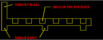
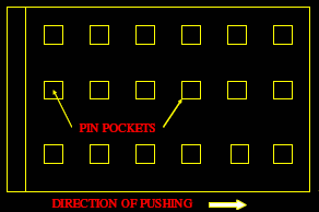
Fig:1 Thrust Bed
BOX CASTING AND PUSHING
- The RCC Box is cast in segments of convenient lengths of Total pushing length.
- The Box section is designed as per IRS / IRC codes of practice for loading. Concrete grade normally kept as M-30.
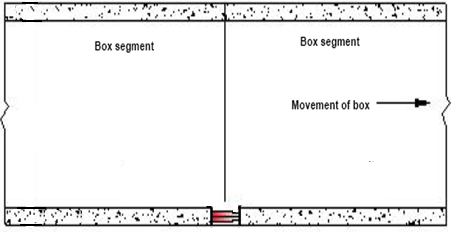
Fig: 2 Precast Box
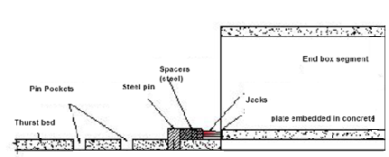
Fig: 3 Precast Box Segment

Fig: 4 Front Shield
After the first box has reached the final position, the second box will be pushed in such a way that a gap of approximately 100mm remains between the units. Cleaning the gap will be done and concrete edges will be roughened, reinforcement will be placed in gap and concreted, if required grouting will be done to make the joint water tight. Suitable admixtures will be used in the concrete used for filling the joint to make them water tight.
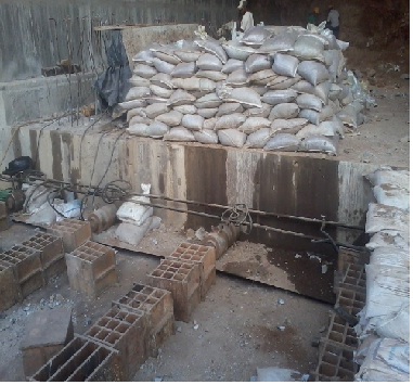
Fig: 5 Hydrulic Jacks
- ANALYSIS AND DESIGN OF THRUST BED
This report contains design of Thrust Bed for precast RCC single box to be pushed inside the embankment for “Proposed Widening of existing RUB, at Chityala village,near Choutuppal in Nalgonda district”, on either side of existing RUB with Box of size 7.5 x 5.5 mt at Railway Km 205/200-300.
CONCLUSIONS
- With the box pushing technique, there is no interruption to the traffic moving around.
- Better quality control due to the provision of precast boxes.
- Quantities will be less as compared to the conventional method of construction.
- The cost of construction is less as compared with the conventional method.
Precast box:
- For the 7.5m span, we got the wall thickness as 750mm.
- For 6.4m clear height, we got the wall thickness as 750mm
Thrust bed:
- We have provided thickness of thrust bed 750mm for length of box 11m.
- The reinforcement details of precast box (tunnel), thrust bed is shown in the Drawing sheet.
- Various unexpected situations are likely to occur during the box pushing operations. Since the safety of running trains is directly affected, proper planning and implementation is essential for smooth completion of work. Advance analysis of site, likely problems that may arise and planning to tackle the same will help the executive for speedy and safe completion of the work.
REFERENCES
- Alberto Zasso, Aly Mousaad Aly, Lorenzo Rosa and Gisella Tomasini “wind induced dynamics of a prismatic slender building with 1:3 rectangular section”
- Proc of Bluff Bodies Aerodynamics & Applications Milano, Italy, July, 20–24 200
- J. A. Amin and A. K. Ahuja “Experimental study of wind pressures on irregular plan shape buildings”
- Ryan Merrick1 and Girma Bitsuamlak “Shape effects on the wind-induced response of high-rise buildings” Journal of Wind and Engineering, Vol. 6, No. 2, July 2009, pp. 1-18
- M. Glória Gomes, A. Moret Rodrigues and Pedro Mendes “wind effects on and around l- and u-shaped buildings” Department of Civil Engineering and Architecture, , Technical University of Lisbon, Portugal
- S. Swaddiwudhipong and M. S. Khan “Dynamic response of wind-excited building using CFD” Proc of Journal of Sound and Vibration (2002) 253(4), 735}754.
- Shenghong Huanga,b, Q.S. Lib,_, Shengli Xua “Numerical evaluation of wind effects on a tall steel building by CFD” Proc of Journal of Constructional Steel Research 63 (2007) 612–627.
- Q.S. Li*, J.Q. Fang, A.P. Jeary, C.K. Wong “Full scale measurements of wind effects on tall buildings” Proc of Journal of Wind Engineering and Industrial Aerodynamics 74Ð76 (1998) 741Ð750.
- Young-Moon Kim, Ki-Pyo You “Dynamic responses of a tapered tall building to wind loads” Journal of Wind Engineering and Industrial Aerodynamics 90 (2002) 1771–174.
To download the above paper in PDF format Click on below Link: