Title: Analysis, Design and Technology That Is Pushing Box Using Land Transportation Implementation Cross (Bridge)
Authors: Lingampally Maithri Varun & S.Manasa
Organisation: Christu Jyothi Institute of Technology and Science
ABSTRACT:
A tunnel is needed in the rail when a channel of God (railway under bridge) to cross the Channel technology, which is pushing for the expansion of existing railway etc.BOX country program has been used. Work trajectory of rail transport, and to pay like it to be done without interruption technology as compared with the conventional method box. Transportation infrastructure of a developing country like India is a key goal. Most of the transportation within the national and Indian Railways. Railway from Bombay to Thane introduced for the first time in India in 1853. In 1951, it became one of the world’s longest network to a single unit system, and as the Indian Railways were nationalized. Each with its own headquarters, the distribution of the number of all zonal railways in 2003, including 65,000 kilometers (40,000 miles) station and track the path of 7500. Sixteen area of 115,000 kilometers (71,000 miles) band . Sixty-eight is a great place for division. Bridge rail as well as road transport is the main link in the system. More than 100 or 150 years, India has more than 1 million in the moment. The service life of a few moments to have outlived. Overall, the bridge before and after the monsoon rains are checked by railway officials. Bridge depending on the situation, rehabilitation or reconstruction will be found in the case of non-been. Any road and rail crossing a level crossing (LC) if there will be, whether natural or high underground can be highly limited, other than that, a bridge (Rob), the road under the bridge (Bridge), ‘respective or less., relative level depends on.
I. INTRODUCTION:
Definition of bridge: The design of the bridge bridge, and the bridge was built, the area where, depending on the nature of the events of the different materials and used to make money.
A bridge is a structure built to span physical obstacles such as a body of water, valley, or road, for the purpose of providing passage over the obstacle. There are many different designs that all serve unique available to build it.
The branch of civil engineering which deals with design, construction and maintenance of bridges is known as bridge engineering.
Classes of bridge crossing:
The classes of crossing are
(a) River crossing
(b) Viaduct: the Bridge across a deep valley which is without perennial water is called a viaduct.
(c)Grade Separation: The Bridge built to cross another route of communication passing at lower level is called grade separation.
1.1. Components of bridge:
The bridge structure may be divided into two major parts:
(a) Sub-structure (b) Super-structure.
For example, a floor in a building from the roof resting on the wall, and the same moment, platform support resting on a road to connect there. And along with this organization, supports a sub-structure and super-structure of the communication path is called the formation of the institutional system.
This sub-structure approach, and the foundation, pillars, piers and wing walls. Super structure further includes the floor structure to support, and the road surface, hand rails or parapet wall, etc.The main parts of a bridge structure are:
- Decking, consisting of deck slab, girders, trusses, etc.;
- Bearings for the decking;
- Abutments and piers;
- Foundations for the abutments and piers;
- River training works, like revetment for slopes for embankment at abutments, and aprons at river bed level;
- Approaches to the bridge to connect the bridge proper to the roads on either side; and
- Handrails, parapets and guard stones.
The components above the level of bearings are grouped as super structure, while the parts below the bearing level are classed as substructure. The portion below the bed level of a river bridge is called the foundation. The components below the bearing and above the foundation are often referred as substructure.
II. Methodology
A. THRUST BED
The thrust bed consists mainly of, (1) Thrust wall, Thrust bed with pin pockets on bed, Keys for additional resistance. The basic feature of the thrust bed is to provide necessary resistance needed for the jacking operation. Thrust bed will have suitable pockets at different locations for housing jacking pins designed for resisting the pushing force exerted by hydraulic jacks as the box is being jacked through the embankment. The typical structural components of the thrust bed proposed to be adopted for the project are shown in drawing no: THB-01-Ro. Over the thrust bed 50mm screeding is to be provided to get exact line, level of the bed for pushing operation. At pockets locations precast cover block are provided to cover the pin pockets during pushing operation.
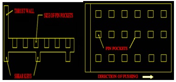
Fig no: 1: THRUST BED
B. Box Casting and Pushing
- The RCC Box is cast in segments of convenient lengths of Total pushing length.
- The Box section is designed as per IRS / IRC codes of practice for loading. Concrete grade normally kept as M-30.
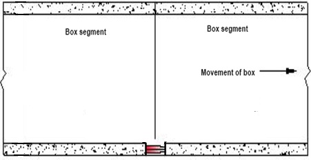
Fig no: 2: PRECAST BOX
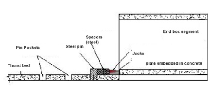
Fig no: 3: PRECAST BOX SEGMENT
C. FRONT SHIELD
It is fabricated for cutting action and to provide support, to prevent caving in of soil. The front shield which acts as a cutting edge will be provided at the front of the first box unit to be jacked. This shield will be fixed to the RCC box through proper anchorage in the box walls with required projection from the face of the box. The end of the box itself is cast in a slope with horizontal projection of required length and the front cutting shield is provided with a projection of @ 1000mm or more as needed, covering the entire periphery of the box. Thus the main feature of the cutting edge is not only to cut the soil, also to retain the soil above the cutting edge.
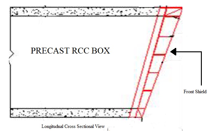
Fig no: 4: FRONT SHIELD
D.REAR SHIELD
Rear shield fabricated from mild steel will be fixed on rear end of the first unit of the box. This shield will be fixed to the RCC box through proper anchorage in the box walls and slab with a projection of 400 to 600 mm. covering entire periphery of the box at the time of casting of the box. It is provided by anchoring steel plates on the face of bottom slab of RCC box to suitably distribute the jacking load.

Fig no: 5: REAR SHIELD
E. PIN POCKETS
- Pin pockets of 0.5m x 0.50m x 0.6m size are provided at suitable spacing for jacking arrangements. The sides of pin pockets are provided with 6mm thick M.S.Plate to take the thrust.
- The pin pockets are then filled with sand and small layer of screed concrete is placed on them to get smooth surface for casting of Box .
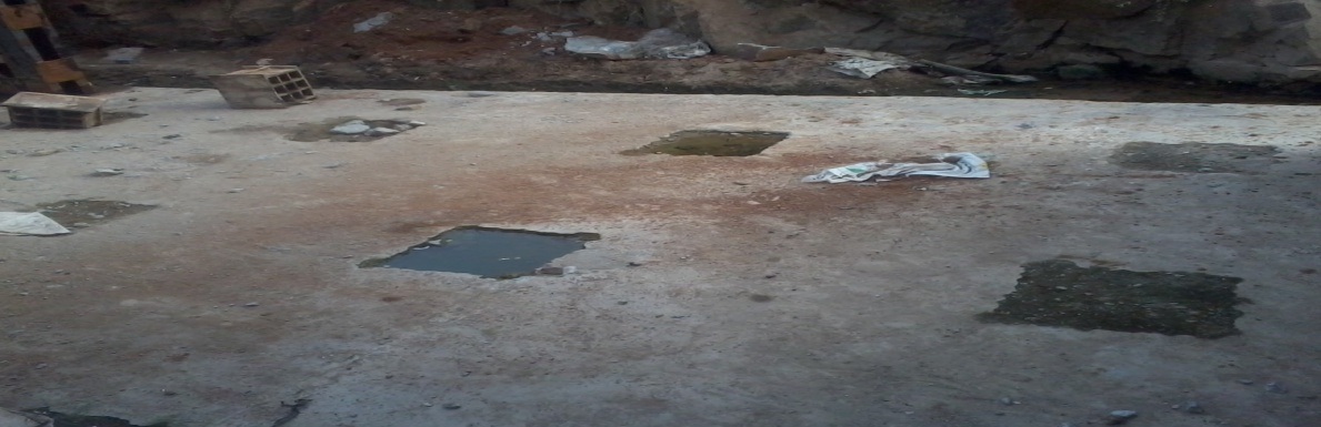
Fig no: 6: PIN POCKETS
F. HYDRAULIC JACKS
The technique of box jacking consists of construction of an RCC thrust bed with necessary jacking pin holes. Steel flats are embedded in the thrust bed over which the boxes will be cast in units and will be jacked by applying pressure through hydraulic jacks which takes reactions against the jacking pins inserted in the pin holes left in the thrust bed.
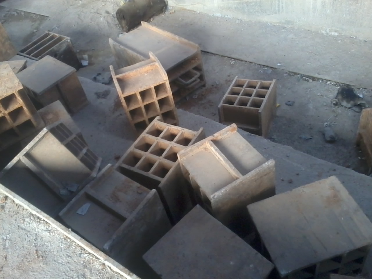
Fig no: 7: PINS
The front unit will be provided with a cutting edge (front shield) and the subsequent units will be provided with intermediate jacking stations at their junction points. To facilitate jacking and to prevent dragging of the soil, drag sheets / epoxy coating will be provided on top of box unit to be pushed to minimize disturbance to top cushion. Before actually starting the jacking operation, excavation near front shield will be done for 200-300 mm. length keeping the front shield top well embedded in the embankment soil at all times. Excavated soil then be removed and box will be pushed by jacks slowly in the gap created. The box will be pushed by hydraulic jacks operated by power pack. This operation of jacking will be continued by adding suitable steel packing boxes and plates between jacking pins and hydraulic jacks till the next row of the pockets in thrust bed is exposed. The jacking pins will then be inserted in these pockets and pushing will be continued till the first segment of box is completely pushed in the embankment. A close monitoring is done of the jacking pressure for different jacks through maintaining correct distribution of hydraulic pressure from power pack to ensure rectification if any misalignment of box unit during jacking operation.
As per specifications, while the pushing of first segment is in progress, required no of boxes will be constructed so that they are available for pushing operation and continuous pushing can be carried out. Other segments of box units, the same will be shifted on the line of alignment of the pushing on thrust bed. These segments of the boxes will be positioned in line and level of box already pushed, by suitably operating the hydraulic jacks and joined to the first segment through the rear shield to form the intermediate jacking station (IJS)> The IJS also enables pushing of individual units one by one by tacking reaction against the rear units, thus reducing the total jacking force needed at a time. For pushing of first box, second box will be hold at rear by pins and jacks will be provided at intermediate jacking stations.
III. RESULTS AND DISCUSSIONS
This report contains design of Thrust Bed for precast RCC single box to be pushed inside the embankment for “Proposed Widening of existing RUB, at Chityala village,near Choutuppal in Nalgonda district”, on either side of existing RUB with Box of size 7.5 x 5.5 mt at Railway Km 205/200-300
Phase – I
3.1.1: DESIGN DATA
RAIL LEVEL =108.907
FORMATION LEVEL=108.232
SIZE OF BOX (2) =7.500X5.650
TOP OF BOTTOM SLAB OF BOX=101.257
TOP OF BOX=107.657
TOP OF THRUST BED (TOP OF SCREED) =100.507
EARTH CUSHION (FROM TOP OF BOX) =0.575
THICKNESS OF TOP SLAB=0.750
THICKNESS OF BOTTOM SLAB=0.750
THICKNESS OF WALL: OUTER WALLS=0.750
OUT TO OUT WIDTH OF BOX=9
OUT TO OUT HEIGHT=7.150
TOTAL PUSHING LENGTH=22
NO OF SEGMENTS=2
LENGTH OF FIRST AND SECOND SEGMENTS=11.00
THICKNESS OF THRUST BED=0.750
CONCRETE GRADE=M25
STEEL GRADE Fy=500
BULK DENSITY OF SOIL=2.10 T/mt3, taken on conservative
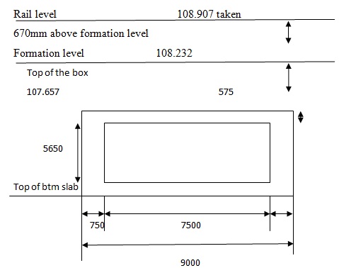
FIG: 9: CROSS SECTION OF BOX TO BE PUSHED
3.1.2: DEAD LOADS
3.1.2.1: VERTICAL LOADS
As normally in railways, total weight of 6750kg/m including track str.is to be taken
Hence for total no of tracks=1×6750=6750 kg/m
Total weight of P.way on top of box unit-=6750x 11(length of box unit)=74250 kgs=74.25T
EARTH FILLING CUSHION:
=0.575X2.1=1.208 T/mt2
So total UDL on top of slab of box will be=1.208×9(o/o width) x11=119.54T
HENCE TOTAL WEIGHT AT TOP=74.25+119.54=193.79 T
4.1.2.2: LOAD ON BOTTOM SURFACE
=load on top +self weight of box
WEIGHT OF BOX=9.00X0.750X2X2.50=33.75
WEIGHT OF VERTICAL WALLS=5.650X1.50X1X2.50=21.19
HAUNCHES=4.00X0.15X0.075X2.50=0.11
TOTAL WEIGHT PER METER=55.05
WEIGHT OF ONE SEGMENT =55.05X11=605.55 T
LOAD ON BOTTOM SURFACE=193.79+605.55=799.3 T
3.1.2.3: EARTH PRESSURE: From bottom of the box
Soil parameters Ɵ = 28.00
δ = 9.33
Active earth pressure co-efficient ka 0.3344
[B] EARTH PRESSURE [Ref: cl – 5.7 of IRS code for sub str. & Foundation]

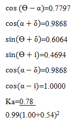
Ka=0.3344
Hence earth pressure at top of box=0.58×0.3344×2.10=0.404 t/sq.mt
Earth pressure at the bottom of box: ht=0.58+7.15=7.73
Earth pressure at bottom of the box=0.3344×2.10×7.73=5.43t/sq.mt
Hence total earth pressure on wall=0.50(0.40+5.43) x7.150=20.840t/m
Hence total load on wall=20.840×11.00=229.24T
IV. CONCLUSION AND SCOPE OF FUTURWORK
4.1: CONCLUSION
- With the box pushing technique, there is no interruption to the traffic moving around.
- Better quality control due to the provision of precast boxes.
- Quantities will be less as compared to the conventional method of construction.
- The cost of construction is less as compared with the conventional method.
4.1.1: Precast box:
- For the 7.5m span, we got the wall thickness as 750mm.
- For 6.4m clear height, we got the wall thickness as 750mm.
4.1.2: Thrust bed:
- We have provided thickness of thrust bed 750mm for length of box 11m.
- The reinforcement details of precast box (tunnel), thrust bed is shown in the Drawing sheet.
- Various unexpected situations are likely to occur during the box pushing operations. Since the safety of running trains is directly affected, proper planning and implementation is essential for smooth completion of work. Advance analysis of site, likely problems that may arise and planning to tackle the same will help the executive for speedy and safe completion of the work.
4.2: Future scope of work:
- This was done for present need, for future expansions box can be extended cast-insitu as there are no tracks, thereby it can be done simpler & easier way, instead of present box pushing technique.
- The present work done is on RCC box, prestressed concrete can also be done, thereby the reinforcement can be reduced greatly, and cost of PSC is more.
REFERENCES:
- Narasimha Rao A.V., (1999), “Characteristics of Fly Ash and Its Application- A Brief Review.”, Proceedings of the National Seminar on Fly Ash Characterisation And its Applications, I.I.Sc., Bangalore, pp 3-14.
- Narayanasamy P., (1999), “ Fly ash as pesticide in agriculture.”, Proceedings of the National Seminar on Fly Ash Characterisation And its Applications, I I Sc, Bangalore pp 162-167.
- Singh R.B., Pallavi Khanna and Agarwal R.K., (1999), “Fly ash utilisation in embankments with geogrids and anchor reinforcement.”, Proceedings of the National Seminar on Fly Ash Characterisation And its Applications, I I Sc, Bangalore pp 179-186.
- Shorff A.V. (1999), “Characterisation of fly ash in cement based grouts”, Proceedings of the National Seminar on Fly Ash Characterisation And its Applications, I I Sc, Bangalore pp 228-235.
- Sridharan A, (2000), “Fly ash characterisation.”, Proceedings in AICTE – ISTE shot term training program on Ground Improvement Techniques, S.J.C.E. Mysore.”, pp AS17-AS33.
- Sridharan A, Pandian N.S., Rajasekhar C., (1996), “Geotechnical characterisation of pond ash.”, Ash ponds and disposal systems, Naroasa publication, pp 97-110.
- Sridharan A, Pandian N.S and Srinivas Rao P., (1998), “Shear strength characteristics of some Indian fly ashes.”, Ground improvement., Thomas Telford, London, U.K.
- Tike G.K., Satander Kumar, Seehra S.S. and Sikdar P.k., (1999), “Utilisation of fly ash in construction of base course for pavements.”, Proceedings of the National Seminar on Fly Ash Characterisation And its Applications, I I Sc, Bangalore pp 222-227
- Vimal Kumar, Mukesh Mathur, Chandi Nath Jha and Gautam Goswami., (1999), “Characterisation of fly ash- A multi facet resource material.”, Proceedings of the National Seminar on Fly Ash Characterisation And its Applications, I I Sc, Bangalore pp 45-50.
To download the above paper in PDF format Click on below Link: