Title: Cryogenic Liquid Nitrogen as a Fuel for Zero Emission Vehicle (ZEV)
Author: Abhilash Vijayrao Nishane, 4th Year, BTech, Mechanical Engineering
College: Kavikulguru Institute of Technology and Science (KITS), Ramtek
ABSTRACT
In an attempt to introduce an alternative choice to the hazardous fossil fuels, a cryogenic heat engine working on a cryogenic fluid, Liquid Nitrogen, is presented. Liquid Nitrogen fulfils most of the requirements that can run a Zero Emission Vehicle. The liquid to gas ratio of Liquid Nitrogen is 1:694 which builds sufficient pressure to drive the specially designed engine. This only requires the exchange of heat from the ambient air to the liquid nitrogen kept at -1960C. The only exhaust is environmentally friendly nitrogen gas. The work is continued to improve the efficiency of the automotive cryogenic engine. As cryogenic engines are reliably and successfully used in space rockets, this helps to improve the automotive performance. This paper is a review of the work done on the development of cryogenic engine, which conceptualize the future of automotive.
Keywords: Alternate fuel, Cryogenics, Automotive, Liquid Nitrogen
1. INTRODUCTION
The world is facing the problem of global warming whose one of the major causes is fossil fuel. Moreover, electric cars too cause harm to the environment because of the toxic heavy metal batteries. According to an analysis by an independent research group, Shrink That Footprint, India is found to be the least green country for electric cars. [3]
As a potential solution to this global problem, the concept of using Liquid Nitrogen, a cryogenic fluid at a temperature of -1960C, is being considered since few years. The Liquid Nitrogen is not basically the source of energy but the energy is stored in it.
The fundamental principle behind the concept is that when the liquid nitrogen is exposed to ambient temperature, it suddenly boils off increasing its volume by about 694 times. This tremendous increase in its volume in very short time is sufficient enough to build high pressure which can drive the engine parts or piston. The power developed will be able to drive a car. If the concept becomes practically successful, it will reduce or eliminate many problems associated with fossil fuels.
It can be a lengthy task to optimize the practical applicability of the concept as everything needs to be designed. Various factors such as safety, cost, etc. should be studied carefully and critically for the successful implementation.
Manning and Schneider [1974] patented a direct drive system utilizing multiple expansions with intermediate reheats followed by a final stage of gaseous recompression and subsequent heating prior to expansion (Brayton cycle). They even went so far as to propose a regenerative device which alternatively routed cold N2 exhaust and warm ambient air through a volume which contained many tension wires connected to a piston that contracted and relaxed under the thermal cycling to extract the last bit of available energy from the working fluid. Apart from these, various patents were also made in later years proposing improved performance of the engine. [2]
2. LIQUID NITROGEN PROPULSION SYSTEM
2.1 WORKING CYCLES
Many different approaches are available to utilize the energy stored in a cryogenic medium. Thermodynamic standard power cycles offer obvious options. A few possible cycles include: the Brayton cycle, the Rankine cycle, two- or three-fluid topping cycles, and even employing a hydrocarbon-fueled boiler for superheating beyond atmospheric temperatures. Further design options include adding reheat or deciding between open or closed systems. Alternatively, the temperature difference might be exploited using a thermoelectric power system. Any of a large number of propulsion and alternative energy storage methods could be combined with cryogenic energy storage to power a hybrid automobile. The ideal engine efficiency can be calculated using conventional Carnot efficiency equation. [6]

Courtesy: Vitt 1998
Figure 1: Temperature-Entropy Diagram for an Open Rankine Cycle
The temperature-entropy diagram for the open Rankine cycle, operated at critical pressure, is shown in Figure 1. Labels 1-2 indicate the pumping process. Because pressurization is occurring in the liquid phase of the fluid, the work required is small in comparison with the available work. Process 2-3 is the pass through the economizer and heat exchanger. Processes 3-4 and 3-4* are the isothermal and adiabatic modes of expansion, respectively. Process 4-1 (or 4′-l) is the liquefaction stage. This occurs remotely at an air processing plant. [6]
2.2 ENGINE PROPULSION SYSTEM
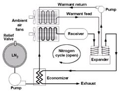
Fig.2 represents the Liquid Nitrogen Propulsion System in which LN2 (Liquid Nitrogen) is stored in a vacuum jacketed storage tank known as Dewar flask. Dewar flask would have appropriate relief features to safely accommodate boil off. The LN2 is pumped through cryopump to the expander through economizer, heat exchanger and receiver. The cryopump would pressurize the fluid to the supercritical operating pressure of the system. Before reaching to the expander the working fluid LN2 is passed through an economizer, which is a kind of heat exchanger in which the heat of exhaust is used to preheat the incoming fluid. After the economizer, the fluid is passed through another heat exchanger where the cold fluid gains heat from the ambient air and liquid nitrogen gets converted to gaseous form in superheated condition.
Courtesy: Knowlen 1997
Figure 2: Schematic of Liquid Nitrogen Propulsion System
The gaseous N2 fills a receiver which minimizes pressure surges in the system due to changing power demands.
The fluid is then sent to the expander where fluid expands to generate mechanical motion. The conventional transmission system transmits the energy to run the wheels and thus the vehicle. The low-pressure exhaust from the expander is passed through the economizer to preheat the incoming cold fluid as stated earlier.
A warmant fluid is pumped through another heat exchanger and is circulated through the expander walls. The function of the warmant fluid is to maintain the expander walls at ambient temperature, otherwise frost formation may take place.
A quasi-isothermal reciprocating expander is suggested for the better utilization of available energy. [2]
3. PROTOTYPES
In 1996, University of North Texas and the University of Washington both developed proof-of-concept vehicles powered by liquid nitrogen without the knowledge of the other’s development (Fig. 3). In the years following, one additional liquid nitrogen powered vehicle was developed by the Kharkov National Automobile and Highway University (KNAHU) along with help from University of North Texas.
The University of Washington’s LN2000 vehicle’s heat exchanger pulls liquid nitrogen from an insulated fuel tank through a series of aluminium tubing coils and specially designed pipes. Engine exhaust and outside air are circulated around the coils and pipes to gradually warm up the nitrogen from a -1960C liquid to an ambient-temperature gas. “The heat exchanger is like the radiator of a car, but it acts in the opposite way. Instead of using air to cool water, it uses air to boil liquid nitrogen into nitrogen gas,” as explained by one of the researchers.
The conversion from liquid to gas expands the volume of the nitrogen 694 times, building sufficient pressure to turn an air motor much like pressure from burning gasoline drives an internal combustion engine. And instead of generating plumes of foul exhaust, the LN2000 emits cold nitrogen gas which freezes water vapour in the air to form small clouds behind the vehicle.

Courtesy: http://www.washington.edu/alumni/columns/dec97/car3.html
Figure 3: LN2000 vehicle during refueling operation
The motor used in the LN2000 prototype consumes about five gallons of nitrogen fuel per mile. Plus it musters a top speed of only 35 kmph and chugs laboriously up hills. [5]
Scientists say the average gas station can be easily converted to liquid nitrogen delivery station.
4. COST, SAFETY AND ENVIRONMENTAL BENEFITS
4.1 COST
Cost is a significant deterrent to public acceptance of most alternative vehicle concepts. Using an open Rankine cycle approach with liquid nitrogen could actually reduce the consumer cost of automobile use compared with gasoline powered cars. The cost of liquid nitrogen is around Rs.5 to Rs.10 per liter in India. This is competitive with gasoline powered as well as battery cars. Additionally, the lack of emission controls and exotic materials would keep cryogenic vehicle prices low. It is expected that 350 litres of LN2 would give a range comparable to a normal internal combustion engine.
4.2 SAFETY
Liquid nitrogen powered automobiles offer many safety advantages over electric vehicles or gasoline powered cars. A liquid nitrogen system would contain no toxic, corrosive, or explosive chemicals. Spilt fuel would not be poisonous at a crash site. The fuel tank is necessarily double walled for insulation, making it a likely candidate for absorbing energy during an impact. Much is also known about the properties and behaviour of common engineering materials at cryogenic temperatures, this adds an extra margin of safety. There is a slight possibility of frostbite or asphyxiation with a liquid nitrogen system in a crash, however, there would be no low frequency magnetic field emissions or other hazards, like those sometimes encountered with electric vehicles.
4.3 ENVIRONMENTAL BENEFITS
Using liquid nitrogen allows the use of an open thermodynamic power cycle. For an open cycle, the exhaust would be a low pressure nitrogen gas released directly into the atmosphere. Since nitrogen gas is the only emission, these cryogenic automobiles would easily meet Indian emission standards and also other global emission standards. Other environmental benefits stem from an avoidance of using heavy metals like lead and nickel for batteries as well as the sulfuric acid or potassium hydroxide used as electrolytes which could pose problems. A dramatic increase in mining, refining, and disposal of these materials for an electric car industry would also pose a significant threat to the environment. Even though the production of liquid nitrogen would use the electrical power grid, commercial electrical power plants are generally cleaner than automobiles. [6]
5. MERITS OF THE ENGINE
(1) The cryogenic liquid nitrogen can make actual Zero Emission Vehicle.
(2) It is a very good alternative to pollution causing fossil fuel cars and toxic and heavy- metal battery cars.
(3) The cost of liquid nitrogen is less.
(4) The energy density of LN2 is 0.62MJ/L.
(5) About 78% of air consists of Nitrogen only.
(6) For Nitrogen, Liquid to Gas expansion ratio is 1:694, thus resulting in tremendous energy merely during phase change.
(7) The vehicle will be lighter and will require low operating and maintenance cost.
(8) Refilling of tank takes only about 10-15 minutes.
(9) The exhaust, Nitrogen itself, is environmentally friendly and can be recycled.
6. RELETED WORK
6.1 QUASI-ISOTHERMAL EXPANSION
A study of the possibility of developing a quasi-isothermal expansion engine had been initiated and has indicated that it would result in the significant gains in the overall energy efficiency of an ambient heated LN2 propulsion system. The results were presented in the research paper (Hertzberg et al. 1997). [2]
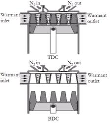
One possibility is a novel piston-head configuration that has the promise of greatly enhancing the heat transfer rate during the first part of the expansion process. This concept consists of a piston with multiple conical fins that fit into a heater core, which is embedded in the top of the expansion cylinder, when the piston is at TDC, as shown in Fig. 4.
A head space over the heater core is used for minimizing the pressure drop associated with distributing the N2 through the passages. The pressure drop through the heater core is assumed to be negligible for the analysis. When the injection valve is opened at TDC, the gas experiences more surface area as the conical fins are withdrawn from the heater core.
No seal is required between the fins and passages; the rings on the cylindrical portion of the piston fulfil this function. Thus a high surface-to-volume ratio is attained at the top of the cylinder where the demand for heat input is the greatest. [2]
Courtesy: Knowlen 1997
Figure 4: Piston having conical fins and heater core inside expansion cylinder
Heat transfer calculations of a quasi-isothermal reciprocating engine that has a heater core imbedded within its expansion chamber indicate that nearly 85% of the performance of an ideal isothermal power cycle can be attained. A representative case indicates that a 2-cylinder engine operating with an injection pressure of 6 MPa at 850 RPM would produce 15 kW and 190 N-m torque. This power plant would enable a zero emission vehicle to have a range of 140 km from 200 liters of LN2. Thus even though this expander concept is far from being optimized, it still can provide an effective power plant for a zero emission vehicle. [2]
6.2 DUAL DOUBLE-ACTING PISTON
To improve the mechanical efficiency of the engine, a dual double-acting piston is found to be useful. It would be beneficial to look for alternative control valves for the high-pressure circuit. It would also be beneficial to develop future simulations that allow variable loads and valve timing, to maximize efficiency at any piston speed. More research to improve high-pressure valves would also be helpful. [4]
6.3 TOPPING CYCLE
Though the use of multiple fluids in the engine increases its complexity, it provides more efficient and optimized performance of the engine and would give long periods of frost-free operation, in addition to increasing the LN2 utilization efficiency. The proper arrangement would increase the total surface area required to transfer the necessary amount of ambient heat into the system, yet minimize the degree of difficulty of preventing frost accumulation because of the corresponding increase in the minimum temperature of the flows within the ambient heat exchanger.
The relatively low peak pressure and temperature of the system reduces the expander wall thickness requirements and thus the thermal impedance and engine mass are also reduced. In closed loop cycle engine, the lost working fluid can be made up on maintenance schedule just similar to that for changing oil in conventional vehicles. It is apparent that there are several complex issues yet to be resolved before an automotive cryogen power plant using multiple fluids can be implemented, however, there do not seem to be any fundamental inhibiting factors that preclude the eventual development of such systems. [1]
The use of liquid nitrogen as a heat sink for several cascaded topping cycles showed that the operating conditions for binary (LN2-CH4) and ternary (LN2-CH4- C2H6) systems can realize specific energies in the range of 200-380 kJ/kg-LN2 and 300-450 kJ/kg-LN2, respectively, depending on the degree of isothermal expansion that can be realized. This results in that the LN2 being used with nearly twice the efficiency of a single expander operating at the same injection pressure. It was found that the best use of LN2 and CH4 was at relatively low injection pressures (< 1.0 MPa) in order to maximize utilization of their heat sink capabilities. [1]
One can refer detailed research data about a particular research or related work from the respective reference papers stated in ‘References’ section.
7. DISCUSSION AND CONCLUSION
Making the use of above explained quasi-isothermal engine with heater core, dual double acting piston and topping cycle will definitely play a vital role in improving the performance of the cryogenic heat engine. Though these factors increase the complexity of the system, the benefits of the cryogenic system should be considered. Further detailed study, simulations, etc. should be promoted.
The Liquid Nitrogen possesses a very good capacity for a promising and viable option as an alternative fuel to power eco-friendly Zero Emission Vehicles. Though various researches have been proposed to improve the efficiency and applicability of the engine, still more research is required to optimize the overall system so that it will be a reality one day.
8. REFERENCES
[1] Knowlen, C., Mattick, A. T., Bruckner A. P., Hertzberg, A. 1998, “High Efficiency Energy Conversion Systems for Liquid Nitrogen Automobiles,” Society of Automotive Engineers.
[2] Knowlen, C., Williams, J., Mattick, A. T., Deparis, H., Hertzberg, A. 1997, “Quasi-Isothermal Expansion Engines for Liquid Nitrogen Automotive Propulsion,” Society of Automotive Engineers.
[3] The Guardian, viewed 01 January 2014, http://www.theguardian.com/environment/blog/2013/feb/07/india-green-country-electric-cars
[4] Thomas B. 2008, “Liquid Nitrogen Propulsion Systems for Automotive Applications: Calculation of the Mechanical Efficiency of a Dual, Double-Acting Piston Propulsion System,” University of North Texas.
[5] University of Washington, viewed 01 January 2014, http://www.washington.edu/alumni/columns/dec97/car3.html
[6] Vitt P. D. 1998, “Operational Characteristics of a Liquid Nitrogen Powered Automobile”, University of Washington.