Title: Decimated Wavelet with Spread Spectrum Approach for Audio Steganography
Authors: B.Venkata Ramana Naik & P.S.S.Sumapriya
Organisation: PNC & VIJAI Institute of Engineering & Technology
ABSTRACT– Steganography is an art of hiding the data into a cover object. Many state of art algorithms proposed to develop an image steganography, video steganography and so on. But, however those algorithms have been suffering from the large storage area and even much complex to embed the data into the video. Here, a novel approach has been proposed by using spread spectrum with decimated wavelet domain. It provides a secure communication over conventional algorithms. The beauty of proposed algorithm is direct sequence spread spectrum, which is used to spread the data into the cover object to make it easy insertion without losing the original information. Experimental analysis shows that the proposed scheme has performed far better than the conventional steganography algorithms.
Key words: steganography, FFT, Wavelets, Cryptography and DSSS
I. INTRODUCTION
The main objective of digital steganography is to hide a secret message within a digital cover object, that means unauthorized persons or others cannot distinguish the hidden message presence [1]. Modern steganography uses the opportunity of hiding information into digital multimedia files and also at the network packet level. We need few elements to hide the information into a cover media as followed by.
- The cover media(C) to hold the data which is to be hidden
- The secret message (M) i.e., any type of data.
- The stego function (Fe) and its inverse (Fe-1)
- An optional stego-key (K) or password may be used to hide and unhide the message [3].
Digital steganography is known as to hide information on the cover of digital objects [3]. Cover objects that are used in digital steganography can vary, for example in the image archive. Steganography algorithms in the image archive have been widely developed. Meanwhile, steganography algorithms in audio archive are relatively few. This paper discusses the application of digital steganography on audio archives using the method of Direct-sequence Spread Spectrum [1]. and Discrete Wavelet Transform techniques. Steganography in the audio archive is not as easy as in the image archive. Unlike the archives of raw images, raw sound files are usually larger. In comparison, the raw image file type and resolution of 1280×800 24bit color (standard resolution of desktop screen) has a size of about 3 MB of data. While the raw audio files with 44.1 kHz sampling frequency, 16 bit stereo channels with 4 minutes duration (the standard duration of song) has a size of about 40 MB of data. The difference is quite large, resulting in the implementation of steganography in audio data becomes more difficult [4]. Fig1. Shows that the block diagram of digital steganography method which includes the cover object, secure key, secret message as the input. Then after we will get a stego audio by applying any algorithm. Now, the message will be extracted and the audio also reconstructed to its original format.
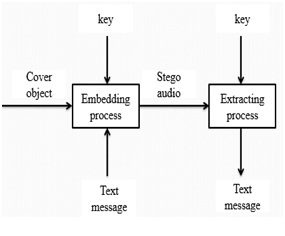
Fig.1 block diagram of digital steganography
In addition, the use of raw audio files (WAV) is less frequent than the raw image files (BMP), because the size in audio files is too large. Therefore, we need such a scheme that enables us to preserve the hidden messages [5], even if the audio files are compressed. In the next section, the author will explain some basic theories that need to be known in advance. In our proposed algorithm we are using Discrete Wavelet transform to convert the audio data domain in to frequency domain of four sub bands (LL, LH.HL and HH). In this four sub bands LL referred as Approximation Coefficients where as remaining three sub bands referred as detail coefficients [5].In the Section II we will discuss Audio Steganography Scheme Using Direct Sequence Spread Spectrum. The proposed algorithm Discrete Wavelet transforms will be discussed in Section III. Experimental results and Conclusion will be discussed in section IV and V respectively.
II. EXISTING METHOD
In this section, we discussed Fast Fourier Transform (FFT) based steganography scheme proposed in [6]. And explained the reasons why the author has used FFT instead of Fourier and short time Fourier transforms.
A. Fourier Transform
The signal can be analyzed more effectively in frequency domain than the time domain, because the characteristics of a signal will be more in frequency domain. One possible way to convert or transform the signal from time to frequency domain is Fourier transform (FT) [6]. FT is an approach which breaks down the signal into different frequencies of sinusoids and it is defined as a mathematical approach for transforming the signal from time domain to frequency domain.
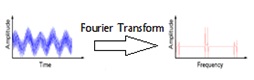
Fig.2. Analysis of FT with an example
FT has a drawback that it will work out for only stationary signals, which will not vary with the time period. Because, the FT applied for the entire signal but not segments of a signal, if we consider non-stationary signal the signal will vary with the time period, which could not be transformed by FT. and one more drawback that we have with the FT is we cannot say that at what time the particular event will has occurred.
B. Short-Time Fourier Analysis
To correct the deficiency in FT, Dennis Gabor in 1946 introduced a new technique called windowing, which can be applied to the signal to analyze a small section of a signal. This adaptation has been called as the Short-Time Fourier Transform (STFT) [7], in which the signal will be mapped into time and frequency information.
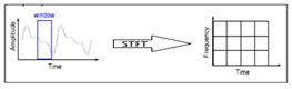
Fig.3. STFT analysis of a signal
In STFT, the window is fixed. So, we this window will not change with the time period of the signal i.e., for both narrow resolution and wide resolution. And we cannot predict the frequency content at each time interval section.
C.FFT Algorithm
This section explains a FFT domain Speech steganography using spread spectrum. Here, FFT is used to transform the audio cover object into the time domain to frequency domain.
Then the signal information will be added to the cover signal by using the spread spectrum. Input message which is to be embedded into the cover object will be converted to binary format based on ASCII codes. Then by using the pseudo noise and key with a gain factor, watermark message will be embedded into the FFT audio.Now, the audio will be integrated with both input audio and the binary message, which is known as stego audio. To reconstruct it and to extract the secret message apply the inverse process of embedding.
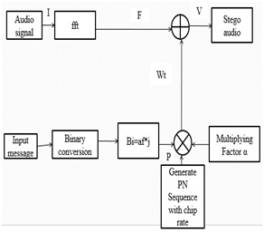
Fig4. Speech steganography using DSSS with FFT domain
III. Proposed SCHEME
3.1. Wavelet Analysis
A wavelet technique i.e., variable windowing has been introduced to overcome the STFT drawbacks. Wavelet analysis allows the use of long time intervals where we want more precise low-frequency information, and shorter regions where we want high-frequency information.
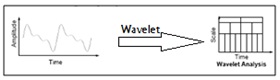
Fig.5. Wavelet analysis with an example
In fig.4 it is shown that the comparison of FT, STFT and wavelet transform by considering an example input signal and how the analysis of transformation techniques will apply to get the frequency information of input signal [8], [9] and [10]. We can observe that in wavelet analysis the graphical representation shows that the wavelet has more number of features than the FT and STFT. Wavelet is also called as multi resolution analysis (MRA). Here’s what this looks like in contrast with the time-based, frequency-based, and STFT views of a signal:
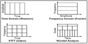
Fig.6. Comparison of FT, STFT and Wavelet analysis of a signal
In this section, the steganography scheme will be explained. Cover object used is the raw audio files like WAV files. Suppose we have byte-sequence information that will be inserted into the cover object, the byte-sequence will be converted into a bit-sequence information. Then we represent these bits into such signal so that if the bit is 1 then the amplitude of the signal is 1, whereas if the bit is 0 then the amplitude of the signal is -1. As shown as follows:
![]() (1)
(1)
Next, open the WAV files and obtain the signal’s amplitude data. The amplitude is represented as 16 bit signed integer value with a range of 215-1 to -215+1. So, for divide this amplitude with a value of 215-1 in order to obtain the range between 1 to -1. Then, by using FFT, the data will be transformed into frequency domain. Now, a random PN sequence will be generated with 1 or -1. If the chip rate of PN sequence is cr, and there are total of n signals for the information signal, then there must be sequences generated. We call the PN sequence P, then
![]() (2)
(2)
Modulate each information signal with the PN sequence until cr times, by multiplying the value. It will produce a signal B which is the distributed signal of A and of course with length cr times its original length. Initially, spread the information in A to B as follows:
![]() (3)
(3)
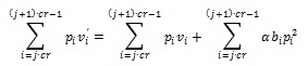
Next, modulate B and P and multiply it by a factor α. Then it will be injected into the cover-media. Suppose, the message that is injected is w, the cover is v and the stego object v’ i.e., in which we have both the message as well as cover-object. Therefore, it can be formulated as follows:
![]()
This scheme will generate noise. If the factor of the amplifier is too large, the noise is also large and may damage the cover-object. So, we should be careful in choose ofthe strength factor and chip-rate. The added signal will be a random signal due to the PN sequence effect which has generated previously. In order for the information to be retrieved, the receiver must generate the same PN sequence. Each cover object signal will be multiplied with the corresponding PN sequence, which can be shown as follows:
If we look at the following terms:

The value of these terms will be close to 0 for a large number of samples (large chip rate). This is because the random value of PN sequence causes the sum of the signal approaching 0 or a certain threshold value.
While the second term:
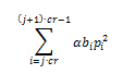
The second term has interesting properties. Because the PN sequence has value 1 or -1, then the result of pi2 is 1.
Thus, the term can be simplified into:

Because we have defined Bi has a value 1 or -1, then we simply conclude that if the term exceed the value of zero, we assume that the information retrieved is 1 and if the value is less than zero, we assume that the information retrieved is 0. This is the reason we choose the domain of B and P. From the previous explanation, we can conclude that the value of must exceed a certain threshold value in order for a clear information retrieval.
3.2 Discrete Wavelet Transform (DWT)
Although the discretized continuous wavelet transform enables the computation of the continuous wavelet transform by computers, it is not a true discrete transform. As a matter of fact, the wavelet series is simply a sampled version of the CWT, and the information it provides is highly redundant as far as the reconstruction of the signal is concerned. This redundancy, on the other hand, requires a significant amount of computation time and resources. The discrete wavelet transform (DWT), on the other hand, provides sufficient information both for analysis and synthesis of the original signal, with a significant reduction in the computation time. The DWT is considerably easier to implement when compared to the CWT [10]. The basic concepts of the DWT will be introduced in this section along with its properties and the algorithms used to compute it. As in the previous chapters, examples are provided to aid in the interpretation of the DWT.
We now look how the DWT is actually computed: The DWT analyzes the signal at different frequency bands with different resolutions by decomposing the signal into a coarse approximation and detail information. DWT employs two sets of functions, called scaling functions and wavelet functions, which are associated with low pass and highpass filters, respectively. The decomposition of the signal into different frequency bands is simply obtained by successive highpass and lowpass filtering of the time domain signal. The original signal x[n] is first passed through a half band highpass filter g[n] and a lowpass filter h[n]. After the filtering, half of the samples can be eliminated according to the Nyquist’s rule, since the signal now has a highest frequency of π /2 radians instead of π. The signal can therefore be sub sampled by 2, simply by discarding every other sample. This decomposition halves the time resolution since only half the number of samples now characterizes the entire signal. However, this operation doubles the frequency resolution, since the frequency band of the signal now spans only half the previous frequency band, effectively reducing the uncertainty in the frequency by half. The above procedure, which is also known as the subband coding, can be repeated for further decomposition. At every level, the filtering and sub sampling will result in half the number of samples (and hence half the time resolution) and half the frequency band spanned (and hence doubles the frequency resolution). Figure 4.1 illustrates this procedure, where x[n] is the original signal to be decomposed, h[n] and g[n] is lowpass and highpass filters, respectively. The bandwidth of the signal at every level is marked on the figure as “f”.
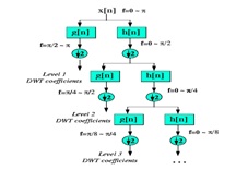
Fig.7 Wavelet decomposition tree
IV. EXPERIMENTAL RESULTS
Simulation results have been done in MATLAB 2011a. We tested the proposed and existing methods for various audio samples with different cr values. In fig.6 FFT based audio steganography has been shown, in which the stego audio is different from the original audio i.e., the unauthorized party can observe the difference in original and stego audio which in results insecure system. We can found that both original and stego audio looks like same in fig. 7, which has achieved by our proposed DWT approach. Also compared the both existing and proposed schemes in fig8and fig9
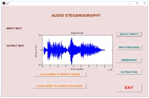
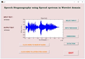
Graphical User Interface Design (GUID):
GUID is a very simple and easy way to execute an application, it will provide a user friendly approach to obtain the required output by clicking the push buttons. Existing speech steganography schemes have been modeled in GUI, which have been shown in a fig10 (a), (b), (c) and (d) respectively. Fig10 (a) is a basic design of speech steganography using FFT algorithm. Selecting the choice of message has been shown in fig10 (b), after embedding the message into a cover object using FFT algorithm has shown in fig10(c). Finally, in fig 10(d) reconstructed and extracted message has been shown.
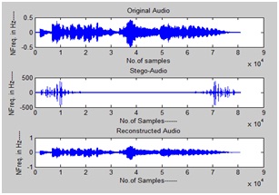
Fig.8 Output of FFT based audio steganography scheme
Fig.9 Output of proposed audio steganography scheme
(a)

(b)
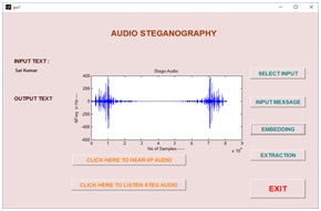
(c)
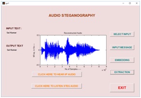
(d)
Fig10. (a) Input audio signal, (b) message selection (c) stego audio using FFT and (d) extracted message and reconstructed speech signal
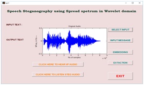
(a)

(b)
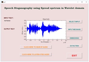
(c)
(d)
Fig.11 (a) input signal (b) message selection (c) stego audio using wavelet domain and (d) reconstructed audio with extracted message
V. CONCLUSION
Based on the GUI test results, we had concluded that the proposed speech steganography in wavelet domain had shown the best results than the conventional FFT algorithm. This method proved that it is very robust against audio manipulation and very safe with the resulting noise is quite small. Also it reduces number computations and does not use any complex equations. It is very simple and easy method to implement even in real time environment.
REFERENCES
- Shouyuan Yang, Zanjie Song and Jong Hyuk Park “High capacity CDMA Watermarking Scheme based on orthogonal Pseudorandom subspace projection”. International Conference on Multimedia and Ubiquitous Engineering, June 2011
- Lionel Fillatre “Adaptive Steganalysis of Least Significant Bit Replacement in Grayscale Natural Images” IEEE Transactions on Signal Processing ,Vol. 60, No. 2, February 2012
- R.Ahirwal, Deep chand Ahirwal and Jpgendar jain “A High Capacitive and Confidentiality based Image Steganography using Private Stego key” International coference on Information Science and applications, Feb 2010.
- Rikzy M. Naguraha “Implementation of Direct sequence Spread Spectrum on Audio Data” International Conference on Informatics Engineering, June 2011.
- Siwar Rekik, Driss Guerchi,Habib Hamam & Sid-Ahmed Selouani “Audio Steganography Coding Using the Discrete Wavelet Transforms”.International Journal of Computer Science and Security (IJCSS), Volume (6) : Issue (1) : 2012
- Bao Liu, Sherman Riemenschneider, An Adaptive Time Frequency Representation and Its Fast Implementation, Department of Mathematics, West Virginia University
- Viswanath Ganapathy, Ranjeet K. Patro, Chandrasekhara Thejaswi, Manik Raina, Subhas K. Ghosh, Signal Separation using Time Frequency Representation, Honeywell Technology Solutions Laboratory
- Michael Unser, Thierry Blu, IEEE Transactions on Signal Processing, Wavelet Theory Demystified, Vol. 51,No. 2,Feb’13
- Valens, IEEE, A Really Friendly Guide to Wavelets, Vol.86, No. 11, Nov 2012,
- James M. Lewis, C. S Burrus, Approximate CWT with An Application To Noise Reduction, Rice University.
To download the above paper in PDF format Click on below Link: