Title: Optimizing the Performance of Modern Telecom Networks using a Novel Beam Sweep DOA method with LMS Algorithm in an Adaptive Smart Antenna
Authors:
Abdul Haque Mohammed, Sr. Assistant Professor, Dept. of ECE,
Aurora’s Scientific, Technological & Research Academy (ASTRA), Bandlaguda, Hyderabad
Prof. Stephen J. Foti, Visiting Professor, School of CEIS
University of Northumbria at Newcastle, United Kingdom
Abstract: A new technique for determining the Direction-of-Arrival (DOA) of mobile users, The Beam Sweep DOA Estimating Technique, is proposed which provides the desired good initial guess for the adaptive weights prior to the start of the LMS algorithm. This Beam Sweep technique literally sweeps the beam over the 120 degree sector and finds the maximum array response for a desired user with a particular digital code while suppressing all other user signals by de-correlation of their digital codes to that of the desired user. Clearly this new technique which is quite straightforward is only practical because 3G networks employ WCDMA. Out of many simulation results obtained in various operational scenarios using MathCAD TM validating the consistency of the suggested methodology one is presented.
Introduction
Mobile telecom networks were originally deployed in the 1980s to provide voice communications only. Owing to rapid advances in technology coupled with an ever increasing demand for “infotainment” services, the architecture of mobile telecom networks has evolved to provide greater capacity and higher data rates. Nevertheless, many of these networks are still capacity limited and new techniques to increase capacity further are sought. The use of adaptive antenna technology offers the feature of multiple simultaneous beams which can track individual mobile users while simultaneously reducing interference from other mobile users. Heretofore, the implementation of smart antenna arrays required complex and expensive hardware. However, with the advent of software defined radio (SDR) techniques, the hardware complexity can be replaced with digital signal processing (DSP) components wherein the functionality of the adaptive array antenna can be changed via uploading modified software. After a review of the required background antenna theory, including phased arrays and adaptive arrays, the subject of adaptive algorithms has been studied. This has led to the selection of the LMS adaptive algorithm to optimize the beam shape. However, the LMS algorithm exhibits slow convergence unless a good initial guess approximation to the adaptive weights can be obtained. A new technique for determining the Direction-of-Arrival (DOA) of mobile users, The Beam Sweep DOA Estimating Technique, has been developed in this project using MathCAD software which provides the desired good initial guess for the adaptive weights prior to the start of the LMS algorithm. This Beam Sweep technique literally sweeps the beam over the 120 degree sector and finds the maximum array response for a desired user with a particular digital code while suppressing all other user signals by the de-correlation of their digital codes to that of the desired user. Clearly this new technique which is quite straightforward is only practical because 3G networks employ WCDMA. Simulations for various operating scenarios have been produced for representative adaptive antenna array architectures showing good results in the improvement of Signal-to-Interference-Ratio (SIR).
Adaptive Algorithms
Sarkar et al. (2003, p.61) tells that “the goal of adaptive algorithms is to estimate the desired response in an adaptive fashion, using a model transfer function”. In adaptive algorithm, the input signal, x(t), is used to track/approximate a desired signal, d(t), through a linear filter, whose impulse response is h(t). According to Liberti, JR. & Rappaport (1999) “adaptive algorithms are used to update the weight vector periodically because it is not desirable to solve the normal equations (MMSE or LS sense) directly” whereas according to Balanis (2006, p.962), “smart antenna systems could gain and apply knowledge via algorithms processed by a digital signal processor (DSP)”. The objectives of a DSP are to estimate: the direction-of-arrival (DOA) of all impinging signals, and the appropriate weights to ideally steer the maximum radiation of the antenna pattern toward the SOI (Signals of Interest) and to place nulls toward the SNOI (Signals not of interest). He then argues that “the work on smart antennas promotes research in adaptive signal-processing algorithms such as DOA and adaptive beam forming” (Balanis, 2006). Adaptive Array Algorithms are generally classified into two categories, they are, Trained Algorithms and Blind Adaptive Algorithm which can be in turn classified into many, El Zooghby (2005). According to El Zooghby (2005) the two useful trained adaptive algorithms are: Least Mean Square (LMS) adaptive algorithm and Recursive Least Square (RLS) adaptive algorithm.
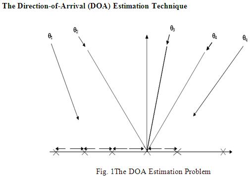
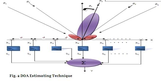
The fig.1 illustrates that several versions of same signal impinge on the receiving elements from different directions. This is because of multipath which means the signal takes multiple paths before arriving at receiver. This is the fundamental principle of all antenna array algorithms and is analysed in Godara (2000). This means there is linear phase delay between elements which means if the first element receive the signal with no delay, the second element will receive it at ∆φ, the third element will receive it at 2∆φ and so on. The phase delay is denoted by “∆φ\””. Fig. 13 (b) depicts the scenario more clearly by showing that the beam is swept in a 120 degrees sector and the output of each element are multiplied by complex weights. The control of these complex weights is in the hand of a digital signal processor chip (DSP) and is shown in Fig.13(c). The resultant signals are then added in a summer to generate a final output, Y. In Fig.13 (b) the elements outputs are denoted by ‘X’, the complex weights are represented by ‘W’, and the weighted output signals are denoted by ‘S’. The final output which is the sum of all output signals is represented by ‘Y’.
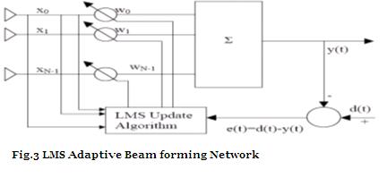
From Fig. 3 it is depicted that the error signal, e(t), is the difference between the reference signal, d(t), and the summer output, y(t). The weights are updated via LMS update algorithm which runs in a signal processor. For a good initial guess of weights the error signal should be as low as possible and this can be achieved when y(t) is close to d(t). In an ideal scenario when y(t) is equal to d(t), there is no error signal e(t).
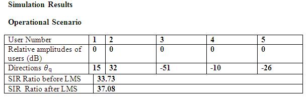
Let us assume that relative amplitudes of all users (both wanted and unwanted) are equal i.e. they all are equally strong. The Radiation pattern of the antenna system after the complex weights have been optimised by the LMS algorithm is shown in the graphs below. A dotted line is shown corresponds to the location of the interferers or the desired user (@10 degrees). The x-y Trace information provided to the right of the plot lists the relative amplitude of the radiation pattern (y-Value) at the angle of the interferer (x-Value) or the desired signal. Review of the plots for this particular operational scenario shows that the LMS algorithm has successfully suppressed all interferers except for the interferer at -26 degrees.
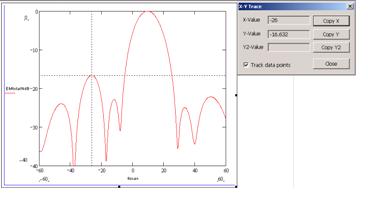
Observations
Signal Strength = -0.289 before LMS
Total Strength of Interferers = -34.019 before LMS
Signal Strength = -8.631*10-3 after LMS
Total Strength of Interferers = -37.088 after LMS
Formula to calculate SIR is, SIR = S- ItotaldB
Discussion of Results
There is an improvement of 3.35dB in signal-to-Interference-ratio (SIR) after LMS Algorithm. This is because the interferer at 32degrees is not too close to the desired user at 15 degrees and the LMS adaptive algorithm is able to distinguish the desired user signal from the unwanted signals.
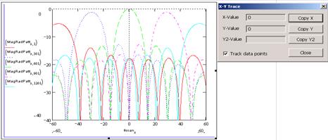
The plots above show the antenna system output (y) as the beam is swept from -60 to + 60 degrees (i.e. 120 degree sector) and this is the Beam Sweep algorithm which finds the DOA of the desired user (10 degrees in this case). The graph above shows the radiation pattern as the beam is swept across the sector (only 5 beam positions shown – actually there are 1201 beam positions.
Conclusions
A new Beam Sweep DOA technique has been developed and simulated which is applicable to 3G mobile networks using WCDMA. The Hybrid Adaptive algorithm of Beam Sweep DOA/LMS has been simulated and for most operational scenarios simulated it has been demonstrated that the SIR has been improved after the LMS algorithm. A computer program written in MathCAD to simulate the new hybrid algorithm has been developed which allows many aspects to be studied by varying various parameters.
References
1. Balanis, Constantine A. (2005) Antenna Theory. 3rd edn. New Jersey: John Wiley & Sons, Inc.
2. Liberti, Joseph C., JR. and Rappaport, Theodore.S. (1999) Smart Antennas for Wireless Communications:IS-95 and Third Generation CDMA Applications. New Jersey: Prentice Hall Inc.
3. El Zooghby, A. (2005) Smart Antenna Engineering. Norwood: Artech House, INC.
4. Sarkar, Tapan K., Wicks, Michael C., Salazar-Palma, Maqdalena and Bonneau, Robert J. (2003) Smart Antennas. New Jersey: John Wiley & Sons Inc.
5. Godara, L.C. (ed.) (2002) Handbook of Antennas in Wireless Communications. Boca Raton: CRC Press LLC.
6. Short, M. (2000) ‘My Generation’, IEE Electronics and Communication Journal. pp. 119-122