Title: Ultrasonic Automatic Braking System For Forward Collision Avoidance With Accelerator Pedal Disengagement Mechanism
Authors: Nishad Vivek Kumbhojkar & Chaitanya Avadhutchintan Kuber, 3rd Year BTech, Mechanical Engineering
College: Sinhgad College of Engineering, Vadgaon
Abstract – This paper presents an ultrasonic automatic braking system for forward collision avoidance with accelerator pedal disengagement mechanism. This system consists of ultrasonic sensors namely ultrasonic wave emitter and ultrasonic wave receiver. The ultrasonic wave emitter is provided in front portion of the car, producing and emitting ultrasonic waves in a predetermined distance in front of the car. Ultrasonic wave receiver is also provided in front portion of the car, receiving the reflected ultrasonic wave signal from the obstacle. The reflected wave (detection pulse) is measured to get the distance between vehicle and the obstacle. Then PIC microcontroller is used to control the servo motor based on detection pulse information, and the servo motor in turn automatically controls the braking of the car. This paper demonstrates the possible use of an accelerator pedal disengagement mechanism in this system, by which the accelerator pedal is automatically disengaged once the braking starts. Thus, even if the acceleration pedal is pressed the vehicle won’t accelerate and this will prevent the collision. This solves the problem of safety in case the accelerator pedal is pressed when the vehicle is expected to brake.
Keywords – Automatic braking system, Ultrasonic sensors, Detection pulse, PIC, Servo motor, Accelerator pedal disengagement mechanism.
1. INTRODUCTION
The number of vehicles is increasing day by day and proportionally the numbers of accidents are also increasing. These accidents are mostly caused by the delay of the driver to hit the brake. To prevent the accidents caused by this delay, ultrasonic braking system is used in automobiles.
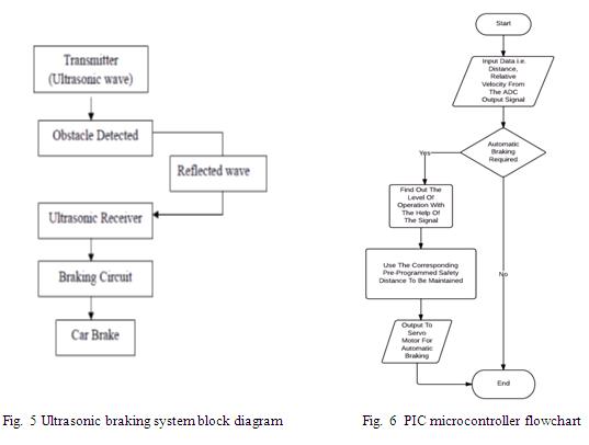
The main target of the ultrasonic braking system is that, cars should automatically brake when the sensors sense the obstacle. This is a technology for automobiles to sense an imminent forward collision with another vehicle or an obstacle, and to brake the car accordingly, which is done by the braking circuit. This system includes two ultrasonic sensors viz. ultrasonic wave emitter and ultrasonic wave receiver. The ultrasonic wave emitter provided in front portion of an automatic braking car, producing and emitting ultrasonic waves in a predetermined distance in front of the car. Ultrasonic wave receiver is also provided in front portion of the car, receiving the reflected ultrasonic wave signal from the obstacle. The reflected wave (detection pulse) is measured to get the distance between vehicle and the obstacle. Then PIC microcontroller is used to control the servo motor based on detection pulse information and the servo motor in turn automatically controls the braking of the car. Thus, this new system is designed to solve the problem where drivers may not be able to brake manually exactly at the required time, but the vehicle can still stop automatically by sensing the obstacles to avoid an accident.
2. OUTLINE OF THE PAPER
This paper is outlined as follows: Section 3 describes the principal components of the ultrasonic automatic braking system. Section 4 describes the methodology. Section 5 describes construction and working of the accelerator pedal disengagement mechanism. Finally, the conclusion is presented in Sections 6.
3. PRINCIPAL COMPONENTS OF ULTRASONIC BRAKING SYSTEM
A. SENSOR –
A sensor is an electrical device that maps an environmental attribute to a quantitative measurement. Each sensor is based on transduction principle which is conversion of energy from one form to another form. There are two important terms related to any sensor –
• Target Angle – This term refers to the ‘tilt response’ limitations of a given sensor. Since the ultrasonic waves reflect off the target object, target angles indicate acceptable amounts of tilt for a given sensor.
• Beam Spread – This term refers to the maximum angular spread of the ultrasonic waves as they leave the transducer [7].
B. TRANSDUCER –
A transducer is an energy conversion device which converts one form of energy into another. In the ultrasonic sensors they are used to convert electrical energy into ultrasonic energy and vice-versa. In this system piezoelectric transducers are used, which create ultrasonic vibration through use of piezoelectric materials such as certain forms of crystals or ceramic polymers. Their working is based on the piezoelectric effect. This effect refers to the voltage produced between surfaces of a solid, (non conducting substance) when a mechanical stress is applied to it. Conversely, when a voltage is applied across surfaces of a solid that exhibits piezoelectric effect, the solid undergoes mechanical distortion.
C. ULTRASONIC SENSOR –
Ultrasonic ranging and detecting devices use high frequency sound waves called ultrasonic waves to detect presence of an object and its range. Normal frequency range of human ear is roughly 20Hz to 20,000Hz. Ultrasonic sound waves are sound waves that are above the range of human ear, and thus have frequency above 20,000Hz. An ultrasonic sensor necessarily consists of a transducer for conversion of one form of energy to another, a housing enclosing the ultrasonic transducer and an electrical connection. These sensors are of two types:
• Ultrasonic Transmitter – Before transmitting the ultrasonic wave, transducer is used to generate the ultrasonic waves. The transducer is given a signal to intermittently produce ultrasonic waves. After that the ultrasonic transmitter sends the waves at a predetermined distance frontward. The maximum range for which obstacle can be detected depends on the range of ultrasonic sensors used.
• Ultrasonic Receiver – If the ultrasonic wave detects the obstacle, it will produce a reflected wave. An ultrasonic receiver is used for receiving the ultrasonic waves reflected from the obstacle. The received ultrasonic wave is converted into a reception signal with the help of a transducer. The signal is amplified by an amplifier (operational amplifier). The amplified signal is compared with the reference signal, to detect components in amplified signal due to obstacles on the road.

D. OPERATIONAL AMPLIFIER AND ADC –
An operational amplifier, usually referred to as op-amp, is a high gain voltage amplifier with differential inputs and a single output. The amplifier’s differential inputs consist of an inverting input and a non-inverting input. The op-amp amplifies only the difference in the voltage between the two inputs called the ‘differential input voltage’. The output voltage of the op-amp is controlled by feeding a fraction of output signal back to the inverting input. This is known as negative feedback. Due to the amplifier’s high gain, the output voltage for any given input is only controlled by the negative feedback [8].
The amplified signal is a square pulse which is given to the ADC. ADC (Analog to Digital Converter) converts input analog signal to corresponding digital signal. The digital signal is given to the microcontroller.
E. BRAKING CIRCUIT –
The processed i.e. the amplified digital signal is sent to the braking circuit.
• PIC (Peripheral Interface Controller) – The microcontroller used is PIC 16F84 which is 8-bit microcontroller. PIC microcontrollers are made by microchip technology. PICs are used in this system due to their low cost and wide availability. The numbers of instructions to perform a variety of operations vary from 35 instructions in low-end PICs to about 70 instructions in high-end PICs. It is programmed by using C language [4].
The signal from the ADC is processed by the PIC microcontroller, and it gives an instruction as an output, based on the condition of the signal, to the servo motor. The signal received from the ADC is also displayed on the LCD display (which gives an audio-visual warning on the windshield in the driver’s field of view), and it gives the distance between the front of the vehicle and the obstacle [1]. The distance value at which automatic braking should start is already stored in the microcontroller. When the measured distance reaches this value, the PIC automatically sends the signal to the servo motor which in turn controls braking through mechanical arrangements.
• Servo Motor –
The output of the PIC is the input of the servo motor. The servo motor allows for precise control of angular position, velocity and acceleration. It consists of a motor coupled to a sensor for position feedback. Thus, it is a closed loop mechanism that uses position feedback to control its motion and final position. The input to it is a signal, either analog or digital, representing the position commanded for the output shaft. The measured position of the output shaft is compared to the command position (the external input to the motor) [4]. If the output position differs from that required, an error signal is generated which then causes the motor to rotate in either direction as needed, to bring the output shaft to the appropriate position. As the required position approaches, the error signal reduces to zero and the motor stops.
The output shaft of servo motor is capable of travelling somewhere around 180 degrees. A normal servo motor is used to control an angular motion between 0 and 180 degrees, and it is mechanically not capable of turning any farther due to a mechanical stop built on to the main output gear. The angle through which the output shaft of the servo motor need to travel is determined according to the nature of the signal
given to the motor as input from the PIC.
The servo motor controls the braking through mechanical arrangements. This is done by using a pair of crossed helical gears and a grooved cylindrical component. The larger gear is mounted on the output shaft of the servo motor and the smaller is mounted on the master cylinder piston rod. Thus, when the output shaft of the servomotor and hence the larger gear rotates in say anticlockwise direction, the smaller gear and hence the master cylinder piston rod rotates in clockwise direction. Due to the groove on the cylindrical component
translatory motion is also produced. This is due to a pin, one end of which is inserted in the groove and the other end is fixed rigidly to a support. Thus, a combination of translatory as well as rotary motion is produced.
Hence, the fluid pressure is applied due to stretching out of the master cylinder piston (in the same manner as that of the brake pedal) thus resulting in braking of the car. The piston returns to the original position when the servo motor output shaft rotates in clockwise direction.
Thus, the speed of the car reduces for clockwise rotation of the smaller gear (i.e. anticlockwise rotation of larger gear and hence the servo motor output shaft). Thus, the servo motor is used to control the brakes, when the PIC gives the signal to the servo motor, based upon the distance measured by means of sensors. This constitutes the braking circuit.
4. METHODOLOGY
There are two cases which occur in real situations:
i. The distance between the front car and the driver’s car is far enough to defend crashing, and the self-velocity is the same as velocity of front car or slower than that of front car. In this case, the driver’s car continues to run without changing its velocity.
ii. Another case is that the distance between the front car and driver’s car is less than the required safe distance at that velocity. Then the auto-braking system forcibly reduces the speed of the driver’s car and eventually the car stops to prevent an accident [6].
The proposed system exhibits four levels of operations:
i. The first level is the high speed operation, above 90km/hr. In this case the safety distance that must be maintained in between the vehicle and the obstacle is considered as 5 meter. Thus, if the sensors detect any obstacle or vehicle within this range the brake is applied automatically and the speed is reduced. As the obstacle is moving away the driver can increase speed manually.
ii. The second level is the medium speed operation, between 60km/hr and 90km/hr. In this case the safety distance that must be maintained in between the vehicle and the obstacle is considered as 4 meter. Thus, if the sensors detect any obstacle or vehicle within this range, the speed is automatically reduced.
iii. The third level is the low speed operation, between 30km/hr and 60km/hr. In this case the safety distance that must be maintained in between the vehicle and the obstacle is considered as 2 meter. Thus, if the sensors detect any obstacle or vehicle within this range, the speed is automatically reduced.
iv. The fourth level is the very low speed operation, below 30km/hr. In this case the safety distance that must be maintained in between the vehicle and the obstacle is considered as 1 meter. Thus, if the sensors detect any obstacle or vehicle within this range, the speed is automatically reduced [3].
5. ACCELERATOR PEDAL DISENGAGEMENT MECHANISM
A. NEED –
We are planning to implement an arrangement in the ultrasonic automatic braking system in which the accelerator will automatically get disconnected, once the braking system starts to function after sensing an imminent collision. Thus, even if the acceleration pedal is pressed when the vehicle is expected to brake, the vehicle won’t accelerate and this will prevent the collision. By doing so, we maximize the guarantee of life safety of those tired or drunk drivers. This mechanism is also advantageous because it may help improve a driver’s reaction time when braking in an automatic transmission vehicle. In this case, the assembly allows the accelerator pedal to be pressed with the right foot and the brake pedal to be pressed with the left foot while preventing the engine power and brake from simultaneously fighting each other. This may increase safety of both the driver and the passengers. We believe that this will also give such system a bigger market space and a competitive edge in the market.
B. CONSTRUCTION AND WORKING –
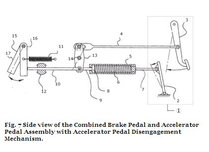
The following list of numbers corresponds to a particular element of the system.
1 – Brake Pedal and Accelerator Pedal Assembly, 2 – Accelerator Pedal, 3 – Brake Pedal, 4 – Connecting Rod, 5 – Spring Housing, 6 – First Spring, 7 – First Pushrod, 8 – Piston, 9 – Second Pushrod, 10 – Third Pushrod, 11 – Second Spring, 12 – Bushing, 13 – Lever, 14 – Fixed Axis, 15 – Engine Control Lever, 16 – First/Disengaged Position of Engine Control Lever, 17 – Second/Engaged Position of Engine Control Lever
Accelerator is operatively connected to an engine control lever that moves between an engaged and a disengaged position. When the accelerator is pressed, the engine control lever moves to the engaged position to accelerate the vehicle. When the accelerator is not pressed, the engine control lever moves to the disengaged position so the vehicle does not accelerate. An accelerator pedal disengagement mechanism moves the engine control lever to the disengaged position when the brake pedal is pushed, which prevents the accelerator pedal from causing the engine control lever to move to the engaged position when both the accelerator pedal and brake pedal are pressed. Thus, the system prevents the accelerator pedal and brake pedal from simultaneously fighting each other.
As shown in the fig. 7, the combined brake pedal and accelerator pedal assembly (1) comprises of an accelerator pedal (2) a brake pedal (3) and an accelerator pedal disengagement mechanism which is controlled by the brake pedal. If the brake pedal is pressed, this mechanism allows the accelerator pedal to be disengaged, if the accelerator pedal is pressed simultaneously. The accelerator pedal disengagement mechanism causes the throttle to return to the idle position and also physically blocks the accelerator from being pressed [9].
The accelerator pedal is connected to one end of the first pushrod (7). The other end of the first pushrod is attached to a first spring (6) in a spring housing (5). The first spring pushes on a piston (8). The piston is connected to a second pushrod (9), which is generally attached perpendicular to the lever (13). The lever is pivoted about a fixed axis (14). The brake pedal is connected to one end of the connecting rod (4). The other end of the connecting rod is attached to the lever as shown in the figure. When the accelerator is pushed, the lever moves to the first position, which corresponds to the accelerator functioning to accelerate the vehicle. When the brake pedal is pressed, the lever moves to the second position, which corresponds to the accelerator not functioning to accelerate the vehicle.
A third pushrod (10) is also attached perpendicular to the lever (opposite to the second pushrod) as shown in the figure. It’s movement is constrained in a single plane by a bushing (12). The third pushrod connects with the bottom end of an engine control lever (15). The engine control lever causes the engine to accelerate. The engine control lever can pivot between an engaged position (17) and a disengaged position (16). The engine control lever is biased in the disengaged position by a second spring (11). When the accelerator is pushed, the lever pushes the third pushrod. The third pushrod pivots the engine control lever to the engaged position. When the driver stops pressing on the accelerator, the lever moves back to the initial position and the engine control lever returns to the disengaged position.

The above graph shows the possible reduction in the response times for different speeds of the vehicle for an automobile without ultrasonic braking system, with ultrasonic braking system and for an automobile with ultrasonic braking system and accelerator pedal disengagement mechanism.
6. CONCLUSION
This paper presents the implementation of an Ultrasonic Automatic Braking System for Forward Collision Avoidance with Acceleration Pedal Disengagement Mechanism, intended to use in vehicles where the drivers may not brake manually, but the speed of the vehicle can be reduced automatically due to the sensing of the obstacles. The ultrasonic sensors are cheaper and the system comprises of a less demanding hardware. The relative speed of the vehicle with respect to the obstacle is estimated using consecutive samples of the distance calculated. It is used by the control system to calculate the action on the brakes, to adjust the speed in order to maintain a safe distance to prevent accidents. This factor, coupled with the fact of lower cost and power consumption of ultrasonic sensors, could facilitate the application and mounting of the system in many low-end vehicles, thus helping to improve safety and offer a hassle free driving experience at a reduced cost. With this future study and research, we hope to develop the system into an even more advanced speed control system for automobile safety, while realizing that this certainly requires tons of work and learning, like the programming and operation of microcontrollers and the automobile structure. We believe that the incorporation of the accelerator pedal disengagement mechanism will maximize safety and also give such system a bigger market space and a competitive edge in the market.
REFERENCES
[1] G.V.Sairam, B.Suresh, CH.Sai Hemanth and K.Krishna Sai,
“Intelligent mechatronic braking system”, International Journal of Emerging Technology and Advanced Engineering, ISSN 2250-2459, ISO 9001:2008 Certified Journal, Volume 3,Issue 4, April 13
[2] Eung Soo Kim, “Fabrication of auto braking system for pre-crash system using sensors”, International Journal of Control and Automation, Volume 2, No. 1, March 2009
[3] Dhanya K R and Mrs R Jeyanthi, “Advanced automatic braking system with sensor fusion concept”, International Journal of Emerging trends in Engineering and Development, ISSN 2249-6149, Issue 2,Volume 3 (April 2012)
[4] Mohd.Shahrizan B. Sahri, ”Ultrasonic car braking systems”,
University of Malaysia, Pahang.
[5] C.Grover, I Knight, F Okoro, I Simmons, G Cooper, P Massie,
B Smith (TRL Limited), “Automated emergency braking systems: Technical requirements, costs and benifits”, Published Project
Report PPR 227, Version: 1.1
[6] Shival Dubey and Abdul Wahid Ansari, “Design and development of vehicle anti-collision system using electromagnet and ultrasonic sensors ”, University of Petroleum and Energy
Studies, India
[7] Hai Wang and Ronghong Xiao, “Automatic car braking system
– based on original reverse warning system”, University of Gaevle
[8] Uttamkumar Dravidam and Sabri Tosunoglu, “A survey on automobile collision avoidance system”, Florida International
University
[9] Ryszard Nawrocki, “Combination brake and accelerator pedal assembly”, US Patent No: US 8308613 B1