Title: SIMULATION MODEL FOR CYLINDER PRESSURE AND INVESTIGATING THE INFLUENCE OF PRESSURE CYCLIC VARIATIONS ON PERFORMANCE OF FOUR STROKE SPARK IGNITION ENGINE
Authors: Santosh Kumar S, Assistant Professor, Department of Mechanical Engineering
College: Raja Reddy Institute of Technology, Bangalore
ABSTRACT
Tracing the pressure history inside the engine cylinder during the process of combustion in a four stroke spark ignition engine through experimental process appears to be cumbersome and economically unviable. Research investigations in the field of automotive are mostly focusing on developing thermodynamic models which are computationally demanding, further the observation of cylinder pressure versus crank angle diagram from a spark ignition engine for successive operating cycles, shows that substantial variations in pressure exists, since the pressure development is uniquely related to the combustion process reducing these cycle by cycle fluctuations in pressure leads to better output, better fuel economy and reduced emissions. In this background the aim of the present work is to develop a thermodynamic one zone simulation model for the analysis of pressure history during the process of combustion in spark ignition engine using Mat lab program and to investigate the influence of pressure cyclic variations on the performance of the engine under different modified conditions such as intake air heating, induction of swirl in intake passage and use of twin spark plug. The model developed here is based on the progressive combustion analysis with modified equations which affect the performance of the engine and is capable of predicting the changes in gas pressure during process of combustion to acceptable levels of confidence.
Keywords: cycle by cycle fluctuations, Mat lab program and progressive combustion
INTRODUCTION
Technologies related to internal combustion engine development are focusing on design of complex engine systems with higher efficiency. To manage the increased complexity, the traditional engine control designs that are based on calibrated maps will require much development time. The model-based techniques can play an important role, since they provide the coupling between inputs, outputs and other relevant parameters and have the potential to significantly reduce the calibration time. Cylinder pressure traces contain information about the work and emission producing process, which are valuable for the engine management system. For some diagnosis and control problems such as pressure cyclic variations, spark advance control, estimation of torque generation and misfire detection it would be beneficial to have information about the available cylinder pressure. One of the key ideas behind the model employed here is based on the observation that the ideal Otto cycle provides valuable information about the compression and expansion process. These two processes are seen in the real measured pressure traces under normal operating conditions. They are similar to the ideal Otto cycle and the similarities are largest early in the compression and late in the expansion cycles. It is characterized by the compression and expansion process which are well defined by the states of the fluid [1].
The variation in gas motion in the engine cylinder during combustion, amount of fuel inducted and mixture composition in each cycle especially near the vicinity of the spark plug have greater influence on pressure cyclic variations. The co-efficient of variation in indicated mean effective pressure is used as the measure of cyclic variability, as it defines the cyclic variability in indicated work per cycle. It has been found that the vehicle driveability problems usually results when co-efficient of variation in indicated mean effective pressure exceeds about 10% [2]. In the present work a thermodynamic one zone simulation model is developed for the analysis of pressure history during the process of combustion and the four stroke engine is modified to operate under different conditions such as intake air heating, swirl induction in the intake passage and use of twin spark plug to study the influence of the above on pressure cyclic variations and engine performance.
MODEL DESCRIPTION
The simulated pressure traces P(θ) is built up by two process pressure traces and an interpolation between these. The cylinder pressure model is divided into three parts: [1], the compression process is well described by a polytropic process. The polytropic process also encapsulates the heat transfer, so that there is no need to explicitly include the heat transfer in the model.
The expansion process is also well described by a polytropic process. The reference point for expansion temperature and pressure is calculated using a constant volume combustion process. The concept of Weibe function provides a convenient way to interpolate between compression and expansion process for obtaining pressure traces during combustion process.
PRESSURE TRACES DURING COMPRESSION PROCESS
It is well accepted that the compression process can be modeled with good accuracy considering a polytropic process. Such a process is described by a polytropic exponent and a value at one reference point such as the intake valve closing (IVC) which gives the following expressions for the compression pressure and temperature. (Assuming pressure at intake valve closing (Pivc) = 1 bar and Polytropic Coefficient for compression process = 1.25) [1].
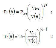
These traces describe the cylinder pressure and temperature up to the point of ignition. The temperature model is also necessary to be included in this approach since it has a direct impact on the second pressure.
ADIABATIC FLAME TEMPERATURE
It is the maximum temperature that can be achieved in the cycle where the combustion is complete and the system is adiabatic. The adiabatic flame temperature depends on many factors such as type of fuel, chemical composition of the reactant mixture and the pressure of reactant mixture. It can be calculated using Newton Rapson iteration technique. Heat of reaction at constant volume Up can be computed using constants of reactants from JANAF tables [3].
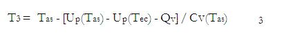
PRESSURE TRACES DURING EXPANSION PROCESS
The expansion process is also modeled as polytropic process with polytropic exponent e.These traces describe the cylinder pressure and temperature from beginning of expansion process to the end of expansion process [1].
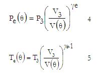
Finally the pressure after the combustion is determined from the ideal gas law
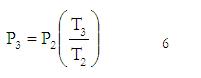
Where, P2, T2 and T3 are determined by equations (1), (2) and (3) respectively.
MASS FRACTION BURNED
The interpolation function is based on Weibe function which is often used to represent the mass fraction burned versus crank angle. [2]
Where θ is the crank angle, θ0 is the start of combustion, ∆θ is the total combustion duration (xb=0 to xb=1), and ‘a’ and ‘m’ are adjustable parameters varying ‘a’ and ‘m’ changes the shape of the curve significantly.
PRESSURE TRACES DURING COMBUSTION PROCESS
It is given by interpolation between pressure compression and expansion pressure traces
Where, Pc (θ) and Pe (θ) are determined by equations (1) and (3) respectively.
CYCLIC VARIABILITY
One important measure of cyclic variability derived from measured pressure data is the co-efficient of variation in indicated mean effective pressure. It defines the cyclic variability in indicated work per cycle. It is given by [2].
RESULTS AND DISCUSSION
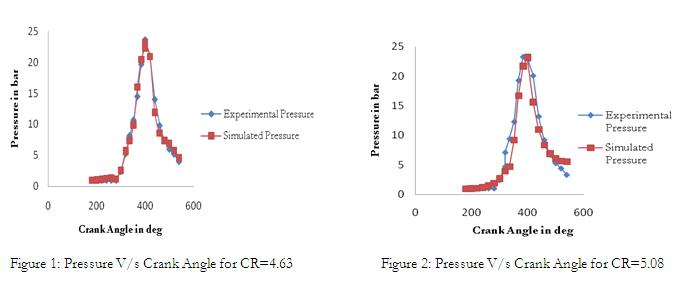
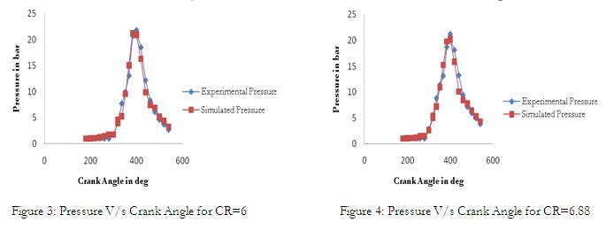
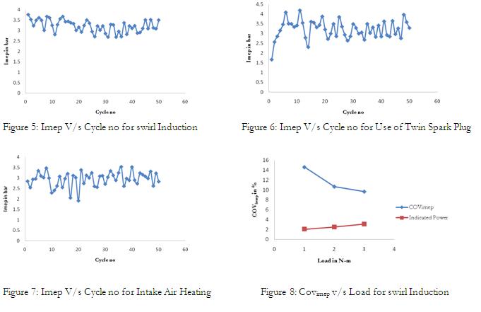
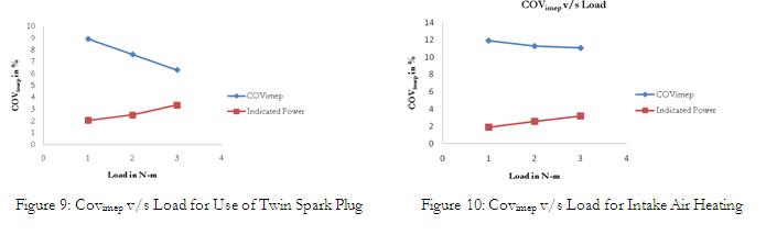
The cylinder pressure model developed here is capable of accurately predicting changes in gas pressure early during compression and late in expansion process (Refer fig 1, 2 and3) as there is no much restriction to gas flow during intake and exhaust process. During the process of combustion at higher compression ratio the model exhibits slightly higher deviation in pressure since the pressure losses are not taken into account. The figure (5, 6 and 7) shows the influence of modified conditions of the engine such as induction of swirl in to intake passage, use of twin spark plug and heating of intake air on pressure cyclic variations for 50 consecutive cycles. It is evident from figures (8, 9 and 10) that co-efficient of variation in indicated mean effective pressure reduces and indicated power increases at higher loads. The best modified conditions are the use of twin spark plug and induction of swirl into intake passage. The figure (10) shows that heating of air has no significant impact on reducing pressure cyclic variations.
APPENDIX-MAT LAB PROGRAM
Clear all; clc;
k=1;
VD=256;
rc=6.0;
a=3.37;
1=13.34;
gamma_c=1.25;
for theta=pi:pi/90:3*pi;
v_theta(1,k)=abs((vd/(rc-1))+(vd/2)*((1/a)+(1-cos(theta))-sqrt((1/a)^2-(sin(theta))^2)));
k=k+1;
end
vc=(1/(rc-1))*256;
v_vivc=vc+256;
p_ivc=1;
pc_theta=(v_ivc./v_theta).^gamma_c;
x=180:2:540;
grid on;
p_out=double(pc_theta);
x_out=double(x’);
v_out=double(v_theta’);
%save (‘output.txt’,’pc_theta’,’x’,’v_theta’,’-ASCII’)
savepc_theta.txtp_out-ASCII
save v_theta.txtv_out-ASCII
%save output pc_theta x v_theta
REFERENCES
1. Lars Eriksson and Ingmar Anderson., 2002, Vehicular Systems, Linkoping University, Sweden, An Analytical
Model for Cylinder Pressure in a Four Stroke Spark Ignition Engine, SAE 2002-01-0371.
2. John B. Heywood, 1998, “Internal Combustion Engine Fundamentals”, Mc Graw – Hill Book Co.
3. V.Ganesan, 1996, Computer Simulation of Spark Ignition Engine Processes”, University press.