Title: Decentralized Control Strategy for Stabilizing VSC Based Smart Grids
Authors: B.Lakshmi Durga, R.Venkata Subbaiah & G.Venkata Suresh Babu
Organisation: SITS, Kadapa
Abstract- This paper presents a novel control topology for VSCs has been developed in the frequency-angle domain to regulate the dc-link voltage while providing synchronizing and damping power components and emulated inertia function to the VSC. These features are highly desirable in VSCs interfacing renewable energy resources, dc MGs and active converter-interfaced loads to weak ac systems. It emulates the behavior of SMs with proper adjustment of the dc-link voltage so the power grid views the VSC dc-link as a virtual rotor. Thus, it can be easily integrated to grids with numerous SMs. It introduces some inertia for the frequency; therefore the stored energy in the dc-link can be used for frequency regulation during contingencies which is the same role of SM’s rotor. It is feasible in both rectifying and inverting modes without reconfiguration i.e., similar to an SM, it can be operate either in motoring or generative mode. The simulation results are provided to validate the controller effectiveness.
Index Terms— Control topology, dc-link voltage regulation, power control, voltage-source converters (VSCs).
I. INTRODUCTION
One of the major challenges facing future power systems is significant reduction in grid equivalent rotational inertia due to the expected high penetration level of EI units, which in turn may lead to frequency-stability degradation. To overcome this difficulty, controlling VSCs as virtual synchronous machines is proposed for power system frequency stabilization by embedding a short-term energy storage to the VSC facilitating power flow to and from to the energy storage device proportional to the variation in grid frequency. In the idea of synchro converter was addressed to emulate the mechanical behavior of a synchronous generator (SG) in inverters. However, the dc-link is considered as an ideal one with infinite energy and the dynamics of dc-link voltage is not considered. Moreover, its application to rectifiers has not been addressed. In methods to emulate virtual inertia in VSCs interfacing wind turbines and HVDC systems, are presented; however, the embedded inertia does not emulate the behavior of an SG. The analogy between voltage-source inverters and SG-based MGs has also been addressed. The aforementioned survey indicates the interest in developing new and improved control algorithms for VSCs to emulate the dynamic behavior of SGs.
Beside overall low inertia, future power systems and MGs will suffer from interactions between fast responding VSCs and slower SMs which may contribute to angle, frequency, and voltage instability. With the expected high penetration level of power converters in future power grids; a power system may face severe difficulty in terms of frequency regulation because of lack of rotational inertia in converter-interfaced generators. Another challenge is that frequency dynamics are not known in the conventional control techniques of VSCs (e.g., voltage-oriented control and direct-power control) which makes it difficult to analyze the angle and frequency stability of a system containing several EI units and conventional synchronous machines (SMs) and line-start motors. Therefore, the development of VSCs with well-defined angle, frequency, and dc-link voltage characteristics (similar to SMs with extension to dc-link dynamics) are of high interest for future smart power systems with a high penetration of VSCs.
Moreover, a general control scheme which is suitable for both rectification and inversion modes without reconfiguration is very attractive in power system applications since bidirectional VSCs can work in generative and motoring modes similar to SMs. The conventional control topologies for three-phase converters are the voltage-oriented vector control and direct- power control. The dq components of the current vector are regulated by a controller generating appropriate values for the converter dq voltage components. A phase locked-loop (PLL) is required to transform current and voltage variables from the abc frame to the dq frame. It is also feasible to implement the controller in the stationary frame or the abc frame using a proportional-resonant (PR) controller. An alternative control strategy is to use direct power control in which voltage components are adjusted based on active and reactive power errors. None of these methods, however, can directly control the frequency and the load angle. To overcome the aforementioned difficulties, in this paper, a comprehensive control strategy is proposed for VSCs. It augments all of the aforementioned requirements in one compact topology which has the following salient features. It emulates the behavior of SMs with proper adjustment of the dc-link voltage so the power grid views the VSC dc-link as a virtual rotor. Thus, it can be easily integrated to grids with numerous SMs.
It introduces some inertia for the frequency; therefore the stored energy in the dc-link can be used for frequency regulation during contingencies which is the same role of SM’s rotor.
It is feasible in both rectifying and inverting modes without reconfiguration, i.e., similar to an SM, it can be operate either in motoring or generative mode. Furthermore, since it provides bidirectional power transfer, even active loads can be used as an asset for frequency stabilization. Therefore, the proposed topology can be an interesting choice for multi-terminal dc networks.
Since the controller has cascaded frequency, angle and dc-link voltage loops, it offers extra damping and synchronizing powers, therefore, it can automatically synchronize itself with the main grid; offer self-synchronization capability; and eliminate the need for a PLL. This feature is a continuation of where the concepts of cooperative droop and nonlinear self-synchronization are proposed. Since dc-link voltage dynamics is inherently taken into account during design and analysis, it presents more practical control topology and design process. In
a simple control strategy for dc-link voltage regulation in frequency domain and polar coordinates is proposed; however, it lacks a comprehensive and general framework for emulating and integrating SM characteristics in VSCs.
This paper presents a comprehensive framework for design of VSCs controllers with SMs behavior while the dc-link acts like a virtual rotor. It yields well-defined dynamics for frequency, angle and dc-link voltage, which in turn makes power system analysis easier. Similar to SMs, it has a fault-ride-through capability. Two different topologies, namely, virtual torque and direct dc-link voltage control strategies, are developed for the frequency control loop. In these topologies, the output power and the dc-link voltage are used as control variables, respectively.
It will be shown that the direct dc-link voltage control presents very good performance with a simple control structure; however, the virtual torque control offers more degrees of freedom to select design parameters due to the presence of an extra power loop. For the voltage control loop, two variants are addressed to realize either a bus or bus operation. A theoretical analysis, simulation, and experimental results are presented to verify the validity and effectiveness of the proposed control strategy.
II. FREQUENCY-ANGLE DOMAIN WITH SYNCHRONOUS MACHINE BEHAVIOR
In this paper, a control topology is proposed in which the frequency, load angle, and dc-link voltage are control variables rather than conventional vector controls which employ current components for dc-link voltage regulation and reactive power control. Thus, direct control of frequency, angle, and dc-link power and voltage is available which in turn provides easier controllability and system analysis. In the following, the control topology is described in detail. One of the main goals in VSC control is to maintain the dc-link voltage constant.
The power-circuit part involves the VSC and the connecting impedance between VSC and the grid and is similar to conventional grid-connected VSC systems. Usually in high power VSCs used in power systems, which are the main scope of this paper, a pure inductor without capacitor is used as output filter. If the VSC is employed to regulate frequency variations during contingencies, an energy storage system can be installed at the dc-link to transfer power from the energy storage device to the grid to damp frequency and angle oscillations. However, for rectifier applications in which no energy storage is used, the active load can be used for power exchange with the grid.
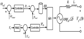
Fig.1. SM principal operation and control concept.
Generally, an SM involves excitation and damper windings mounted on the rotor and three-phase windings in the stator. Although the damper windings significantly improve transient performance in terms of synchronism and damping capabilities, and the reluctance torque increases power density of an SM, in this paper, the model of a round rotor synchronous motor without damping windings is considered.
In fact, the effect of damping and synchronizing powers can be emulated by the control functions in the VSC without physical damping components as in conventional SMs. The voltage generation principle in a synchronous-VSC is similar to back-EMF generation in SGs shown in Fig.1. In this case, the reference torque is equivalent to the generated electrical torque of an equivalent SM.

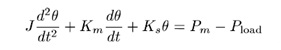
The question is how to set the torque reference to achieve a desirable output dc-link voltage because, unlike synchronous motors where electrical torque is automatically generated to overcome the load and friction torque at synchronous speed, the main objective of a VSC control is to regulate the dc-link voltage (e.g., in bi-directional VSCs and in VSCs interfacing renewable resources). Toward this, an extra dc-link voltage and virtual torque control loops are added to the core control loops to adjust the dc-link voltage as a function of the virtual torque error. The frequency dynamics are similar to those of an SM in which the rotating shaft is opposed by a viscous damping proportional to the frequency deviation plus a damping torque proportional to the load angle deviation. The extra angle loop here offers an additional angle shift which enhances system stability.
III. SMALL-SIGNAL ANALYSIS
To investigate the dynamic performance and transient response of the system, a small-signal model is developed. The small-signal analysis gives insights on how controller variables variation affects the stability and convergence characteristics of the controlled variables. It also helps in optimum tuning of controller parameters to reach the best tradeoff among design objectives. The design values of the controller parameters can be obtained using the small-signal analysis to achieve satisfactory transient response. The given model has been used to extract the family of the system eigen value plots. This figure reveals that, by increasing from 0.001 to 0.005 s, the damping of the overall system is improved, whereas further increment of the cutoff frequency results in lower stability margin. In other words, by proper adjustment of the highest damping can be fulfilled. Usually, the most inner controller bandwidth is selected to be less than 20% of the switching frequency. Unlike real SMs, the rotational momentum and friction factor can be selected equal to values that are not possible for physical electrical machines. The larger means the higher stored energy; however, to provide this energy, more short-term energy storage or equivalently inertia is required. If sufficient energy storage devices are not available, lower values for are recommended to have faster response.
IV. SIMULATION RESULTS
This section presents detailed simulation results of the proposed control system. The simulated system is shown in Fig. 2. Simulation studies are carried out in the MATLAB/SIMULINK environment. Different conditions in both generative and rectification modes are considered to show effectiveness and generality of the controller in all cases.
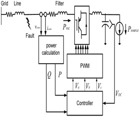
Fig.2. Schematic view of the simulated system
The system is simulated under various scenarios of VSC operating conditions. Three scenarios are taken into account; load/generation power change, dc-link voltage reference change, and grid voltage change in both rectifying and inverting modes.

Fig.3(a) simulation results for rectifying mode Real power
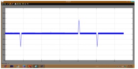
Fig.3(b) simulation results for rectifying mode Frequency

Fig.3(c) simulation results for rectifying mode Reactive power
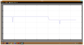
Fig.3(d) simulation results for rectifying mode DC voltage
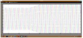
Fig.3(e) Current wave forms for the case of load power increment
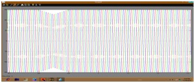
Fig.3(f) output filter voltage wave forms for the case of load power increment
The time-domain responses are in agreement with the eigen value analysis presented, which indicates the effectiveness of the designed controller.
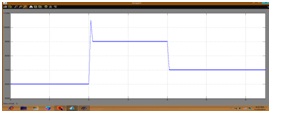
Fig.4(a) simulation results for inverting mode Real power

Fig.4(b) simulation results for inverting mode Frequency
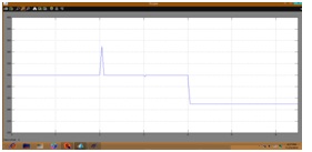
Fig.4(c) simulation results for inverting mode DC-link voltage
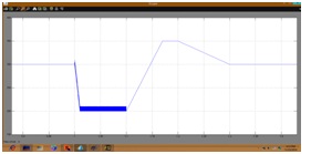
Fig.5(a) Fault –ride-through capacity of the synchronous-VSC DC-link voltage
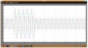
Fig.5(b) The instantaneous output filter voltage waveform.
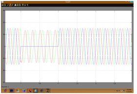
Fig.5(c) Fault –ride-through capacity of the synchronous-VSC Instantaneous output filter voltage.
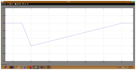
Fig.6(a) system response of the vector control for the case of the load power increment DC-link voltage.
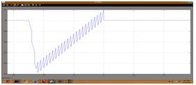
Fig.6(b) system response of the vector control for the case of the load power increment VSC’s frequency.
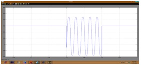
Fig.7 (a) system response during the fault using the vector control Dc-link voltage.
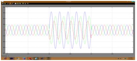
Fig.7(b) system response during the fault using the vector control Instantaneous currents
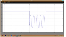
Fig.8 DC-link voltage variation during the fault using the vector controller with fault resistance R=1Ω
V. CONCLUSION
A novel control topology for VSCs has been developed in the frequency-angle domain to regulate the dc-link voltage while providing synchronizing and damping power components and emulated inertia function to the VSC. These features are highly desirable in VSCs interfacing renewable energy resources, dc MGs and active converter-interfaced loads to weak ac systems. It is a new control topology implemented in the frequency angle domain, which simplifies converter integration and analysis in grids with conventional SGs. The controller introduces some inertia and dynamics for frequency. In fact, the power grid views the dc-link capacitor as a virtual rotor with virtual inertia. The stored energy in the dc-link is employed to damp frequency oscillations during contingencies. Since the controller presents damping and synchronizing power dynamics, similar to SMs, it can automatically synchronize itself with the grid and tracks its variations, thus there is no need for a PLL after initial synchronization. In the modeling and design process, the dc-link voltage dynamics are taken into account which provides a more general and accurate control framework. The controller offers fault-ride-through capability which enhances the overall system reliability.
VI. REFERENCES
[1] A. A. A. Radwan and Y. A. R. I. Mohamed, “Linear active stabilization of converter-dominated DC microgrids,” IEEE Trans. Smart Grid, vol. 3, no. 1, pp. 203–216, Mar. 2012.
[2] Eur. Center for Power Electron., “Strategic research agenda on intelligent power electronics for energy efficiency,” 2008 [Online]. Available: http://www.ecpe.org/
[3] N. Flourentzou, V. G. Agelidis, and G. D. Demetriades, “VSC-based HVDC power transmission systems: An overview,” IEEE Trans. Power Electrom., vol. 24, no. 3, pp. 592–602, Mar. 2009.
[4] T. Noguchi, H. Tomiki, S. Kondo, and I. Takahashi, “Direct power control of PWM converter without power-source voltage sensors,” IEEE Trans. Ind. Appl., vol. 34, no. 3, pp. 473–479, May/Jun. 1998.
[5] F. Blaabjerg,R. Teodorescu,M.Liserre, and A. V. Timbus, “Overview of control and grid synchronization for distributed power generation systems,” IEEE Trans. Ind. Electrom., vol. 53, no. 5, pp. 1398–1408, Oct. 2006.
[6] J. Driesen and K. Visscher, “Virtual synchronous generators,” in Proc. IEEE Power and Energy Soc. Gen.Meeting—Conversion and Delivery of Electrical Energy in the 21st Century, Jul. 20–24, 2008, vol. 1, pp. 1–3.
[7] Q.-C. Zhong and G.Weiss, “Synchronverters: inverters that mimic synchronous generators,” IEEE Trans. Ind. Electron., vol. 58, no. 4, pp. 1259–1267, Apr. 2011.
[8] M.Kayikci and J.V.Milanovic, “Dynamic contribution ofDFIG-based wind plants to system frequency disturbances,” IEEE Trans. Power Syst., vol. 24, no. 2, pp. 859–867, May 2009.
[9] M. F. M. Arani and E. F. El-Saadani, “Implementing virtual inertia in DFIG-based wind power generation,” IEEE Trans. Power Syst., vol. 28, no. 2, pp. 1373–1384, May 2013.
[10] J. Zhu, C. D. Booth, G. P. Adam, A. J. Roscoe, and C. G. Bright, “Inertia emulation control strategy for VSC-HVDC transmission systems,” IEEE Trans. Power Syst., vol. 28, no. 2, pp. 1277–1287, May 2013.
To download the above paper in PDF format Click on below Link: