Title: Power Quality Enhancement in Micro Grids Using Harmonic Compensation by PV Interfacing Inverter
Authors: P.B.Adi Shakthi, Seetha Chaithanya & G.Venkata Suresh Babu
Organisation: SITS, Kadapa
Abstract— In this paper using distributed generation system in residential areas to improve power quality. To compensate a harmonics resonance in residential areas, active and passive filters are used in distribution network. To improve the distribution generation (DG) using photovoltaic interface inverter the harmonics was compensated. The increased non-linear loads in today’s typical home are a growing concern for utility companies. This situation might be worsened by the harmonic resonance introduced by the installation of capacitor banks in the distribution network. To mitigate the harmonic distortions, passive or active filters are typically used. In general increasing utilization of electronic devices in homes is a growing concern for utility companies due to harmonic distortions. Besides the degrading power quality, the harmonic current flow may interfere with the adjacent telephone lines. The harmonics in a residential system is difficult because of the dispersed nature of the residential loads. In this paper, the potential for using photovoltaic (PV) interfacing inverters to compensate the residential system harmonics is explored. A system model including the residential load and DG is first developed. An in-depth analysis and comparison of different compensation schemes based on the virtual harmonic damping impedance concept are then carried out. The effects of the capacitor banks in the system are also studied. The effectiveness of the harmonic compensation strategies under different conditions is verified through analysis and simulations.
Index Terms— Distributed generation (DG), photovoltaic (PV), power quality improvement, harmonic compensation, renewable energy, residential distribution system.
I. INTRODUCTION
Renewable energy is generated from natural resources which are replenished such as wind, wave, solar, biomass and tidal power. The demand for renewable generation has grown exponentially in the last few years. This rush of renewable generation has been attributed to the increase of fossil based energy costs and the push for cleaner sources of energy in the country. Governments and companies around the world are investing heavily in developing technologies to harness the power of clean renewable energy sources because of their potential to produce large quantities of energy without generating greenhouse gases which can contribute to climate change During recent years, due to the increase in fossil fuel prices and the environmental problems caused by the use of conventional fuels, we are reverting back to renewable energy sources. Renewable energies are inexhaustible, clean and they can be used in a decentralized way (they can be used in the same place as they are produced). Also, they have the additional advantage of being complimentary, the integration between them being favorable. The Penetration level of distributed generation (DG) units is increasing on power distribution networks across the world .With the increasing concerns on conventional energy cost, energy security and greenhouse gas emissions , the energy industry is experiencing fundamental changes as more distributed energy-resource-based distributed generation (DG) units are being connected to the grid. In order to improve power quality, power industries are concentrating more on Distributed Generation Systems.
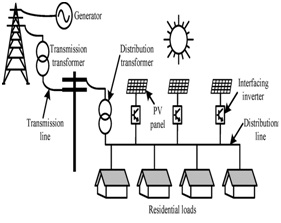
Fig.1. Residential system with PV installations
Besides the degrading power quality, the harmonic current flow is also a concern for the telecommunication industry as this harmonic current flow may interfere with the adjacent telephone lines. Compensating the harmonics in a residential system is difficult because of the dispersed nature of the residential loads. Therefore, lump compensation at a few locations is not every effective. As a result, finding an effective way to compensate the dispersed load harmonics and improve the residential distribution system power quality is an important topic. In addition to having increasing concerns about power quality, the power industry is experiencing a paradigm shift as more renewable energy based distributed generation (DG) systems are being connected to the power distribution network. As shown in Fig. 1, these PV systems are connected to the grid through DG-grid interfacing inverters, which are used mainly to convert the voltage from the energy source to the voltage that can be readily connected to the grid, and to transfer the real power to the grid. If controlled properly, these DG-grid interfacing converters are able to provide a number of ancillaries Functions such as power factor compensation, voltage support, flicker mitigation, system harmonic compensation, and unbalance voltage compensation in addition to the primary function of real power injection. This potential for ancillary services can be realized by properly utilizing the available apparent power rating from the interfacing inverters. Doing so is feasible as most of the time these inverters are not running at their maximum power due to the intermittent nature of renewable energy (such as PV). The concept of system harmonic compensation using grid interfacing PV inverter has been reported in the literature. However, the system considered in the previous work is usually too simple (e.g., the system is often comprised of only a few lines and loads) to provide realistic results.
II. SYSTEM MODELING
In this work, the PV inverters are controlled as virtual harmonic impedance at the harmonic frequencies to compensate the residential system harmonics. Therefore, before the residential system model and harmonic compensation performances are discussed, the virtual impedance control concept is introduced in this section. Virtual impedance emulates the effect of physical impedance, without the need to connect any physical component to the system. In the DG inverter control, the virtual impedance is implemented by modifying the voltage or current reference or the PWM signal, through digital control of the inverters. Virtual impedance can be either at the fundamental frequency or at the harmonic frequencies. The fundamental frequency virtual impedance is used mainly to facilitate DG power flow control and grid disturbance ride through. The harmonic virtual impedance is mainly used for active damping and distribution system harmonic compensation. As this paper is focused on the system harmonics compensation using PV inverters, the virtual harmonic impedance and its control schemes are discussed in the following subsections.
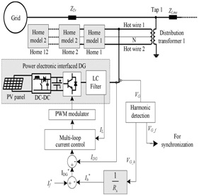
Fig.2. Harmonic damping with R-APF based DG.
The virtual harmonic resistance control, the PV inverters work as R-APF. A block diagram of the system harmonic damping control is shown in Fig. 2. The PV system in this example is a two-stage conversion system, which includes a DC-DC converter that steps up the PV output to the DC link voltage level with maximum power point tracking (MPPT) control, and an inverter that connects the system to the grid. The PV system output current reference has two components: (i) the fundamental component, which is produced from the DC link voltage control and power factor control loops (which are not shown in Fig. 2 as the focus here is harmonics compensation), and (ii) the harmonic components, which are used for harmonic compensation.
The modeling of the distribution system is presented in the following section, and the aforementioned PV inverter system is then connected to the developed distribution system model to investigate the harmonic compensation performance.
To avoid the effects of different current control techniques on the PV inverter, controlled current sources at the desired harmonic frequencies are used in the rest of this paper to model the PV inverter with virtual impedance control. In this section, the system model including the residential house load, distribution systems with PFC capacitors, and PV inverters (with virtual harmonic impedance control) is first developed. The developed models are then used in the rest of the paper for the analysis of harmonic distortions and compensation performances by using different approaches. Residential PV system locations are usually not controllable as they depends on which residence has the system installed. However, coordinated control of the PV inverters in a system is possible, and an optimal compensation strategy should be identified to obtain the best harmonic compensation result. The two strategies for harmonic compensation using the DG interfacing inverters are the end-of-distribution-feeder (or end of line) compensation, and distributed compensation. In a distribution system with multiple PV systems, the end-of line compensation strategy can be implemented by assigning harmonic compensation priority to the PV inverters connected at the end of the feeder. On the other hand, the distributed compensation approach can be implemented by operating all PV inverters in the harmonic compensation mode with equal priority. Capacitors are often installed in distribution systems for voltage regulation and reactive power compensation. These capacitors may cause harmonic resonances and affect the harmonic compensation performance. This section extends the analysis in the previous sections to include the effects of PFC capacitors. The voltage profile along the distribution line with a capacitor is influenced by the capacitor location and the capacitor’s reactance value. Generally, a capacitor connected at the end of a distribution network provides the best performance for improving the voltage profile along the distribution line by improving the power transfer capability, voltage regulation, and power factor. However, the most efficient capacitor placement also depends on the load, load power factor, line parameters of the distribution network, and reactance value.
III. SIMULATION RESULTS
Time domain simulations of an 11-node system were also conducted by using Matlab/Simulink to verify the above analysis using the developed models. In the time domain simulations, the home model has harmonics up to the 13th, so the situation will involve the relatively low frequency range. The harmonic current and voltage content throughout the distribution line for different compensation strategies are shown which show that the low-order harmonics are lower throughout the entire distribution line for end-of-line compensation.
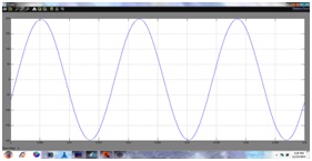
Fig.3. Current through distribution line
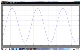
Fig.4. current flowing from node 11 to primary side of distribution transformer 11
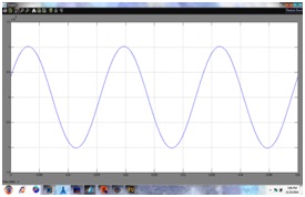
Fig.5. Distribution voltages at node 1
It shows the Distribution voltages at node 1 in distribution system by using the PV interfacing inverter and shows the improvement of the power quality. It shows the Voltage at node 11 in the distribution system using PV interfacing inverter and shows the improvement of the power quality.
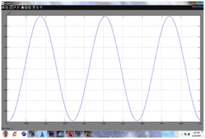
Fig.6. Voltage at node 11
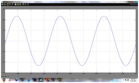
Fig.7. hot wires 1 to neutral voltage of distribution transformer 11
It shows the hot wires 1 to neutral voltage of distribution transformer 11 in the distribution generation system using the PV interfacing inverter and also shows the reduction of the harmonics. It shows the hot wires 1 to neutral voltage of distribution transformer 11 in the distribution system by using the PV interfacing inverter and shows the reduction of the harmonics.
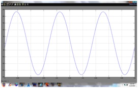
Fig.8. hot wire 1 to hot wire 2 voltage of distribution transformer 11
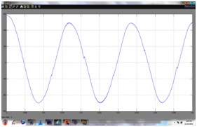
Fig.9. current flowing through hot wire 1 of distribution transformer 11
The current flowing through hot wire 1 of distribution transformer 11 in the distribution system by using the PV interfacing inverter and shows the harmonic compensation with the increasing of the power quality. It shows the distribution generation system harmonic current at 11th node in the distribution system using the PV interfacing inverter and shows the improvement of the power quality.
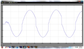
Fig.10. DG harmonic current at 11th node
Capacitors are often installed in distribution systems for voltage regulation and reactive power compensation. These capacitors may cause harmonic resonances and affect the harmonic compensation performance. This section extends the analysis in the previous sections to include the effects of PFC capacitors. It shows the Current through distribution line in the distribution generation system using the PFC capacitor and it is shows the less power quality improvement than the PV interfacing inverter.
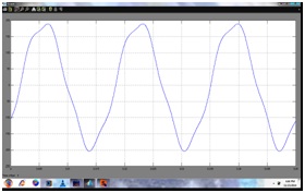
Fig.11. Current through distribution line
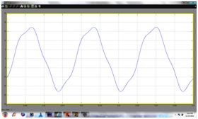
Fig.12. current flowing from node 11 to primary side of distribution transformer 1
The current flowing from node 11 to primary side of distribution transformer 1 in the distribution generation system using the PFC capacitor and it is shows the less power quality improvement than the PV interfacing inverter. The current flowing through hot wire 1 of distribution transformer 11 in the distribution generation system using the PFC capacitor and it is shows the less power quality improvement than the PV interfacing inverter.
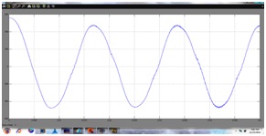
Fig.13. current flowing through hot wire 1 of distribution transformer 11
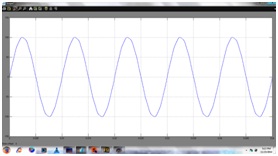
Fig.14. DG harmonic current at 11th node
IV. CONCLUSION
In this paper, we explored the idea of using residential system DG-grid interfacing inverters as virtual harmonic resistances to damp the system harmonics and improve the power quality. An in-depth analysis and comparison of different harmonic compensation schemes were conducted to provide a guide for determining whether distributed compensation or end-of-line compensation should be used. After such a determination has been made, proper priorities can be assigned to the inverters in the distribution system for optimal compensation performance. Specifically, the analysis and simulation results showed that the end-of-line compensation provided better damping for low order harmonics, whereas distributed compensation provided better damping for high-order harmonics if the equal equivalent rating of the DG was maintained. In the system without PFC capacitors, this crossover frequency was quite high, and end-of line compensation performed better. However, the presence of capacitor in the system could significantly reduce this crossover frequency to around the 7th order harmonic, so the decision about which compensation strategy to use must be made according to the system load characteristics. Moreover, the effects of capacitor sizes, line impedance, and length on the crossover frequency were also analyzed in this paper. With the information about a distribution system, the crossover frequency between the two compensation strategies can be determined by using the model developed in this work, and proper priority can be assigned to the PV inverters at different locations. In our future work, we will consider a supervisory control system of the DGs with communication in order to control the participation from each PV inverter automatically according to the identified priority. Also, to provide an accurate effectiveness analysis of the harmonics compensation by using PV inverters throughout the day/season/year, the use of a statistical home model of a residential system and solar irradiance historic data could also be considered.
V. REFERENCES
[1] J. Arrillaga and N. R. Watson, Power System Harmonics, 2nd ed. Hoboken, NJ, USA: Wiley, 2003, pp. 176–180.
[2] K. Wada, H. Fujita, and H. Akagi, “Considerations of a shunt active filter based on voltage detection for installation on a long distribution feeder,” IEEE Trans. Ind. Appl., vol. 38, no. 4, pp. 1123–1130, July/Aug 2002.
[3] European Photovoltaic Industry Association (EPIA) “Annual report 2011”, Mar. 2012, pp. 5–7.
[4] Global Wind Energy Council (GWEC) “Global wind report, annual market update 2011”, Mar. 2012, pp. 4–7.
[5] M. Triggianese, F. Liccardo, and P. Marino, “Ancillary services performed by distributed generation in grid integration,” in Proc. IEEE Int. Conf. Clean Electr. Power, 2007, pp. 164–170.
[6] M. I. Marei, T. K. Abdel-Galil, E. F. El-Saadany, and M. M. A. Salama, “Hilbert transform based control algorithm of the DG interface for voltage flicker mitigation,” IEEE Trans. Power Del., vol. 20, pp. 1129–1133, Apr. 2005.
[7] M. Prodanovic, K. D. Brabandere, J. V. D. Keybus, T. Green, and J. Driesen, “Harmonic and reactive power compensation as ancillary services in inverter-based distributed generation,” in IEE Proc. Gener. Transm. Distrib., May 2007, vol. 1, pp. 432–438.
[8] Y. W. Li, D. M. Vilathgamuwa, and P. C. Loh, “Microgrid power quality enhancement using a three-phase four- wire grid-interfacing compensator,” IEEE Trans. Ind. Appl., vol. 41, pp. 1707–1719, Nov. –Dec. 2005.
[9] C. H. Lin, W. L. Hsieh, C. S. Chen, C. T. Hsu, and T. T. Ku, “Optimization of photovoltaic penetration in distribution systems considering annual duration curve of solar irradiation,” IEEE Trans. Power Syst., vol. 27, no. 2, pp. 1090–1097, May 2012.
[10] A. Capasso,W. Grattieri, R. Lamedica, and A. Prudenzi, “A bottom-up approach to residential load modeling,” IEEE Trans. Power Syst., vol. 9, no. 2, pp. 957–964, May 1994.
[11] C. Zhe, F. Blaabjerg, and J. K. Pedersen, “Hybrid compensation arrangement in dispersed generation systems,” IEEE Trans. Power Del., vol. 20, no. 2, pp. 1719–1727, Apr. 2005.
[12] Y. A.-R. I. Mohamed, “Mitigation of dynamic, unbalanced, and harmonic voltage disturbances using grid-connected inverters with filter,” IEEE Trans. Ind. Electron., vol. 58, no. 9, pp. 3914–3924, Sept. 2011.
[13] M. Prodanovic, K. D. Brabandere, J. V. D. Keybus, T. Green, and J. Driesen, “Harmonic and reactive power compensation as ancillary services in inverter-based distributed generation,” IEE Proc. Gener. Transm. Distrib., vol. 1, no. 3, pp. 432–438, May 2007.
[14] A. B. Nassif, J. Yong, and W. Xu, “Measurement-based approach for constructing harmonic models of electronic home appliances,” IEE Proc. Gener. Transm. Distrib., vol. 4, no. 3, pp. 363–375.
[15] Y. J.Wang, R.M. O’Connell, and G. Brownfield, “Modeling and prediction of distribution system voltage distortion caused by non-linear residential loads,” IEEE Power Eng. Rev., vol. 21, no. 7, p. 71, Jul. 2001.
To download the above paper in PDF format Click on below Link: