Technical Paper Title: Energy Saving through the use of Variable Air Volume systems and PID Controllers
Authors:Anushka Gulati, 2nd Year BTech,CSE
College: Indira Gandhi Institute of Technology, Guru Gobind Singh Indrapastha University, Kashmere Gate, New Delhi
1. Abstract
In most of the big residential buildings and manufacturing plants, temperature and humidity controls are very important. For certain industries the nature of the product gets significantly altered if deviations occur from temperature and humidity set points. For maintaining these set points, HVAC system is installed. HVAC stands for “heating, ventilating, and air conditioning”. The three functions of heating, ventilating, and air-conditioning seek to provide thermal comfort and acceptable indoor air quality at reasonable installation, operation, and maintenance costs.
Most of the industries currently use the “Constant Volume Systems”. Constant volume systems are less energy efficient because in these systems the motors that are connected to the supply fans operate at full speed all the time and the variations in the thermal requirements of the room are satisfied by varying the temperature of the constant volume of air that is supplied to the room. This paper proposes the use of “Variable Air Volume” systems where the volume of air supplied to the room is varied based on the heat load present in the room and the temperature at which the air supplied enters the room is kept a constant. In such a system, electrical energy is significantly lower as compared to the constant volume systems as the speed of the supply fan is altered using a Variable Frequency Drive and it thus runs below full
speed most of the time. The above system is controlled using PID Controllers.
2. Introduction
Cooling load (or heat gain) is the amount of heat energy to be removed from a room by the HVAC equipment to maintain the house at indoor design temperature when worst case outdoor design temperature is being experienced. There are two types of cooling loads:
- sensible cooling load
- latent cooling load
Sensible load arises out of temperature difference between outside and inside
conditions
RSH= 0.0204 [ cmm] * [Ti- Ts]
Sensible load determinants:
- solar gain through walls, glasses, windows etc.
- infiltration load and fresh air load
- load due to heat released by machines, lighting equipment,
- load due to people in the area
Latent load arises out of moisture content difference
RLH=50* cmm * [ wi- ws]
Determinants of latent load are moisture released by people, infiltration, and fresh air load.
Variable Volume Systems
Variable air volume (VAV) is a technique for controlling the capacity of a heating, ventilating, air-conditioning (HVAC) system. Because the supply air temperature, in this simplest of VAV systems, is constant, the air flow rate must vary to meet the rising and falling heat gains or losses within the thermal zone served. Thus in a variable volume system, thermal requirements of the room are satisfied by varying the volume of air delivered to the room at a constant temperature. These systems reduce cost over constant volume systems.
Air handling units (AHU’s)
It is an integrated piece of equipment consisting of fans, heating and cooling coils, aircontrol dampers, filters and silencers. The purpose of this equipment is to collect and mix outdoor air with that returning from the building space. The air mixture is then cooled or heated, after which it is discharged into the building space through a duct system. It is a thus used to condition and circulate air as part of the HVAC system.
The main components of an AHU are:
Blower/fan
Air handlers typically employ a large squirrel cage blower driven by an AC
induction electric motor to move the air. The blower may operate at a single
speed, offer a variety of pre-set speeds, or be driven by a Variable Frequency
drive so as to allow a wide range of air flow rates.
Heating/cooling elements
Depending on the location and the application, AHU’s may need to provide
heating, or cooling, or both to change the supply air temperature. Large
commercial AHU’s contain coils that circulate hot water or steam for heating,
and chilled water for cooling. The hot water or steam is provided by a central
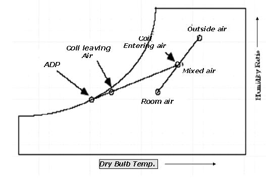
boiler, and the chilled water is provided by a central chiller. In summer and monsoon the only equipment for cooling and dehumidification in the AHU is the cooling coil. This is because air is dehumidified by cooling it below its dew point. The mean surface temperature in the cooling coil varies from one end to the other end. The effective surface temperature of the cooling coil is called the Apparatus dew point (ADP) temperature. It can be considered as that uniform surface temperature which would produce the same leaving
state of air as the varying surface temperature. During the heat exchange process between air and water in the AHU, some of the air passes through the cooling coil unaffected. This fraction of air that is not cooled by the cooling coil is called the Bypass factor of the coil.
Mixing chamber
In order to maintain indoor air quality, air handlers commonly have provisions to allow the introduction of outside air into, and the exhausting of air from the building. In temperate climates, mixing the right amount of cooler outside air with warmer return air can be used to approach the desired supply air temperature. A mixing chamber is therefore used which has dampers controlling the ratio between the return, outside, and exhaust air.

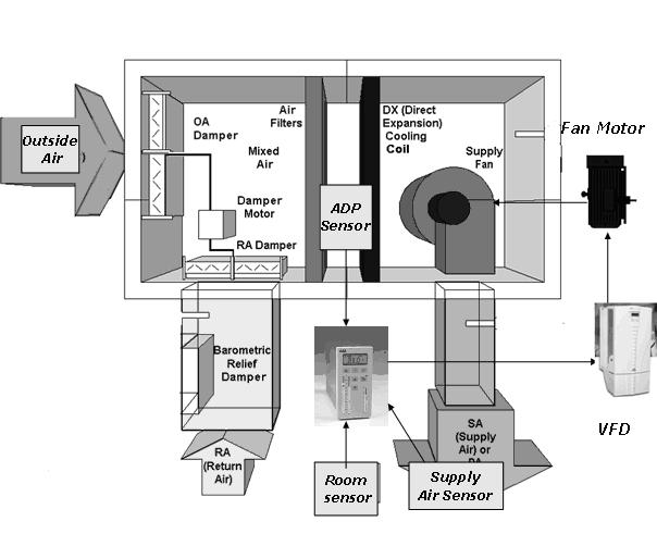
A typical Air Handling Unit (AHU)
Psychrometrics is the field of engineering concerned with the determination of physical and thermodynamic properties of gas-vapor mixtures. The most common system of interest, however, is mixtures of water vapor and air because of its application in heating, ventilating, and air-conditioning.

Cooling Coil Process on a Psychrometric Chart
3. Energy Savings through Speed Control
The characteristics of centrifugal equipment such as blowers and supply fans vis-à-vis
flow can be explained by the following basic equations:
- Flow is proportional to speed (F α N)
- Pressure is proportional to square of speed (P α N2)
- Therefore Power = F × P α N3
The power consumption thus the “Cube Law”, which means that by reducing the speed to 80% of the maximum value the power consumption, will be reduced to about 50%. As an example, at 80% speed the power consumption is (0.8)3 or 0.512 or 51.2% A small reduction in speed therefore produces a very significant reduction in power consumption. Fixed air systems using constant speed fans with dampers or inlet guide vanes controlling the airflow consume a lot of energy by constantly running the motor at full speed. Energy saving of up to 50% or more is often possible in a typical installation after using a Variable Frequency Drive.
4. Control logic for air flow variation
- Flow rate of air in cubic meters of air/min,cmm=mass flow rate(ma)*60/d
where ma is in kg/s and d is density of air
- Temperature of mixed air, Tmix= (mra* Ti + moa*To)/(mra + moa)
where: mra stands for mass rate of air returning from the room in kg/s
moa stands for mass rate of outside air in kg/s
Ti stands for room temperature
To stands for outside temperature
- For the heat exchange process occurring between air stream and the chilled water stream:
ma (rate)* Cp (air)*(Ti-Ts) = mw (rate)*Cp(water)*(Texit – Tinlet)
where: Cp(air) and Cp(water) are the specific heat capacities of air and
water respectively
Ts is the temperature of air being supplied to the room
Texit and Tinlet are the chilled water exit and inlet
temperatures respectively
- Room sensible heat load (RSH) = 0.0204 * cmm * (Ti-Ts)
where 0.0204 is a constant of conversion
- Cmm = RSH/0.0204 * (Ti – Tadp) x (1- B.F.)
where: Ti stands for room temperature
Tadp stands for the apparatus dew point temperature of the
cooling coil
B.F. is the bypass factor of the cooling coil
Incremental heat load on the system will cause the room sensible heat to change to RSH1temperature to change from the set point to Tfd. In a constant volume system, there is no other manipulated variable so as to compensate for this change in Apparatus dew point temperature from Tadp to Tadp.
- In a constant volume system,
RSH1 = RSH x (Tfd – Tadp1)/(Ti-Tadp)
Variable Air Volume (VAV) system gives the flexibility to manipulate air flow rate from cmm to cmm1 using variable frequency drives (VFD’s).
At new cmm, Tfd converts to Ti and Tadp1 to Tadp
Changed flow rate cmm1 = RSH x (Tfd-Tadp1)/(Ti-Tadp)2
Thus, we vary flow rate of air to keep Tadp and Tsupply almost constant as sensible load on the system changes
5. Controllers
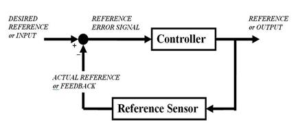
A Controller is used to correct the error between the set point variable and the actual measured process variable.

Block Diagram of a Controller
PID Control
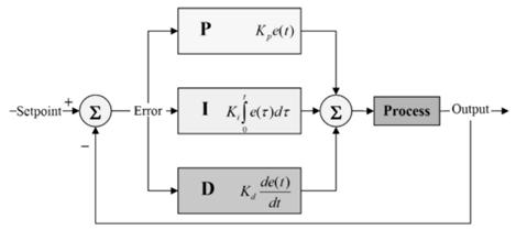
The PID algorithm is the most popular feedback controller used. It is a robust easily understood algorithm that can provide excellent control performance despite the varied dynamic characteristics of process plant.
Proportional value determines the reaction to the current error. The Integral value determines the reaction based on the sum of recent errors and the derivative determines the reaction to the rate at which the error has been changing. The weighted sum of these three actions is used to adjust the process.
Transfer Function of a PID Controller = Kp + Ki/s + Kd * s
where: Kp is the proportionality constant
Ki is the integral constant and
Kd is the derivative constant
Adaptive Control
Adaptive control is one where the Control law is continuously modified to cope with the fact that the parameters to be controlled are slowly varying or uncertain.
In the adaptive flow controller, the controller parameters would be determined continuously from field-fed information from sensors and the controller would accordingly schedule its future action. The PID controller takes in sensor inputs and process them using preprogrammed control algorithms in its EPROM. The Controller then gives an analog output corresponding to the Variable frequency drive (VFD) which is then used to control the speed of the motor connected to the supply fan.
6. Determining the PID Constants using Transient Processes
Room load is the indeterminate quantity and needs to be eliminated so that the controller works only transient changes. For that we need to do a transient analysis of equations by transforming them into Laplace domain.
For the temperature rise inside the room
M (air)* Cp (air) * (dTi/dt) = room load – ma (rate)* Cp (air)*(Ti-Ts)
where: M(air) stands for the mass of air inside the room in Kg
As we are concerned only with the incremental rate of change of the mass flow rate of air i.e. d (ma (rate))/ dt,
- We differentiate the above equation and then
- Transform it into Laplace domain to obtain
Cp(air)* ( s2Ti –s*T(steady state)) = d(roomload)/dt – [d (ma(rate))/ dt] * Cp(air)*(Ti-Ts) ——(A)
where: dx/dt = s( X)- X(steady state) and d2x/dt2= s2(X)- s * X(steady state)
- Room sensible heat load or roomload (RSH) = 0.0204 * [mass flow rate( ma(rate)) * 60 / d]* (Ti-Tsupply)
Taking derivative of equation,
d(RSH)/dt = 0.88* d (ma (rate) )/ dt*( Ti-Tadp)—————————-(B)
where: 0.88 is a constant of conversion
Eliminating d (roomload)/dt from the above equations A and B and using
d (ma (rate))= ( s ma (rate) –ma(steady state)) we get,
Cp(air) ( s2Ti -s T(steady state)) = 0.88* ( s ma (rate) – ma(steady state)) *( Ti-Tadp) –(s ma (rate) – ma(steady state)) * Cp (air) * (Ti-Ts)
Signal of ma (rate) is the input which is to be fed into the fed to the Variable
frequency drive. Air flow rate would be varied taking T adp, T supply, Ti into
account. Tsupply, Ti, Tadp will be fed into the air flow controller with proper control algorithm to vary flow rate of air by giving analog signal to VFD.
The final system would look like

AHU along with PID Controller, Sensors and VFD
7. Conclusion
A variable air volume system design using PID controllers and sensors is proposed in the paper for obtaining the desired set-point temperature in the room space. The control flow algorithm has been formulated to obtain the PID constants for the controller. For feeding in the various temperature and other necessary input signals, sensors are needed to be installed at strategic places. Variable air volume systems are obtained using a variable frequency drive. The power saving advantage of such drive is clearly evident. However care must be taken to ensure that the supply fan speed is not lowered below a certain minimum level in any given circumstances as that would cause ventilation problems in the enclosed space.
References
1. K. Sakkas, “Presentation of automation and control devices for saving energy in building units” International Workshop on Energy Performance and Environmental Quality of Buildings, July 2006,
2. Keith E. Elder, P.E., “Air Conditioning Design: Psychrometrics & Coil Load
Calculations”, 2002
3. A. Bhaduri, “The Use of Variable Frequency Drives in Existing HVAC
Installations”, July-September 2001
4. www.wikipedia.org


