Authors:
K.Naga Sujatha, Associate Professor, Dept of EEE, JNTUHCEJ, Karimnagar.
K.Vaisakh, Professor, Dept of EE, AU Engg College ,Visakapatnam.
Abstract
This paper presents the design and implementation of neural network controller for reducing torque ripples in brushlessDC (BLDC) motor drive with trapezoidal back-emf. The performances of the proposed neural networkcontroller are compared with the corresponding fuzzy PI controller and conventional PI controller. Simulation results are used to show the abilities and shortcomings of the proposed speed regulation scheme for brushless dc motor which is considered as a highly nonlinear dynamic complex system. Matlab/Simulink software was used to simulate the proposed model.
Keywords –Brushless DCMotor Drive BLDC, Fuzzy Logic controller, Neural Network controller.
1.INTRODUCTION
A brushless DC motor is one of a small-scale motor used in small electric devices such as CD players, hard disk drives, or even small electric cars. Its rotor is mounted with permanent magnet. There is no need for extra field excitation. This motor is well-known and popular for position and speed control drive applications [1, 2]. The key advantage of this motor over other types in the same rating is higher ratio of produced torque per weight, faster response, accurate position control, lower moment of inertia, less maintenance, etc [3, 4].
The construction of modern brushless motors is very similar to the ac motor, known as the permanent magnet synchronous motor. The stator windings are similar to those in a poly phase ac motor, and the rotor is composed of one or more permanent magnets. Brushless dc motors are different from ac synchronous motors in that the former incorporates some means to detect the rotor position (or magnetic poles) to produce signals to control the electronic switches as shown in Fig.1. The most common position/pole sensor is the Hall element, but some motors use optical sensors.
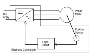
Fig.1 Brushless DC Motor Drive
In variable speed operations of BLDC motor, the PI control is still the most used control. This is because of its simplicity and ease of design. However, it has disadvantages that the performance depends to proportional and integral gains. Therefore, when the operating condition changes such as disturbances, load changes and motor’s parameters variations, the re-tuning process of control gains in necessary. Controllers using artificial intelligent tools, such as fuzzy logic and neural network can be applied to overcome foregoing problems. Different intelligent controllers such as Fuzzy logic controllers (FLC) and neural network controllers have been explored. They may control the speed directly or as indirectly adjust the gains of PI controller.
This paper presents an implementation of neuralnetwork controller for improving the transient responses to torque disturbance and speed reference following of the BLDC motor drive. Simulation results are used to show the abilities and shortcomings of the proposed method as compared with the conventional PI and fuzzy controllers.
2.BLDC MODELING
- Mathematical Model of BLDC Motors
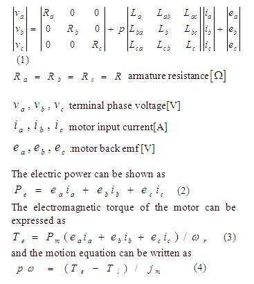
Modeling of a BLDC motor can be developed in the similar manner as a three-phase synchronous machine [1,2]. Since its rotor is mounted with a permanent magnet, some dynamic characteristics are different. Flux linkage from the rotor is dependent upon the magnet. Therefore, saturation of magnetic flux linkage is typical for this kind of motors. As any typical three-phase motors, one structure of the BLDC motor is fed by a three-phase voltage source. The source is not necessary to be sinusoidal. Square wave or other wave shape can be applied as long as the peak voltage is not exceeded the maximum voltage limit of the motor. Similarly the typical mathematical model of a three-phase is described
The voltage equation of the BLDC motor can be written as:
where
La ,Lb, Lcare the self-inductance of three phases windings,
Lab,Lba,Lbc,Lcb,Lca,Lac are the mutual inductance by different windings,
ea,eb, ecdenote the inducedelectro-motive forces,
Pnis the number of pairs of BLDC motor,
ωrdenote the angular velocity,
Tlis the load torque,
J m is the rotational inertia
The overall system configuration of the 3-phase BLDC motor drives is shown in Figure 2.It comprises of six functional blocks Speed controller block generates the current demand to maintain the speed at reference value. Back-EMF voltage block calculates the phase back-EMF voltages according to rotor position. Phase current block calculates the phase current. Current control block controls the phase current via hysteresis current control and generates the switching signals for Inverter. In Inverter block, phase voltages are obtained. The inverter topology is six-switch voltage-source configuration with constant DC-Link voltage (VMA). The PWM three-phase inverter operation can be divided into six modes according to the current conduction states. The three phase currents are controlled to take a form of quasi-square waveform in order to synchronize with the trapezoidal back-EMF to produce the constant torque. In each time only two phases are excited, so it is possible to use only one current sensor which is placed in DC-link voltage.
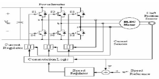
Fig.2 BLDC Motor Drive with Speed Controller
3.SPEED REGULATION SCHEMES
Human abilities in controlling the complex systems, has encouraged scientists to pattern from human neural network and decision making systems. Firstly the researches began in two separate fields and resulted in establishment of the fuzzy systems and artificial neural networks. There are primarily three concepts prevailing over the intelligent control:
* Fuzzy Logic Control
* Neural Network based Control
- A) Fuzzy Logic Controller
In the first concept, the controller is represented as a set of rules, which accepts/gives the inputs/outputs in the form of linguistic variables. The main advantages of such a controller are:
(1) Approximate knowledge of plant is required
(2) Knowledge representation and inference is simple.
(3) Implementation is fairly easy.

where wr(k) is the reference speed and wr(k) is the actual rotor speed.
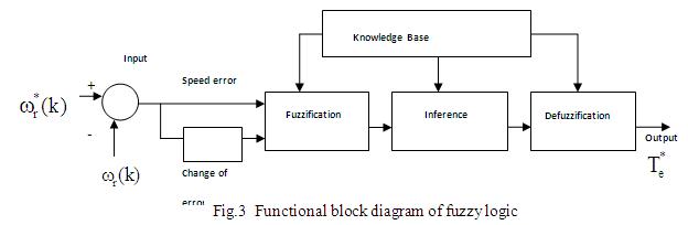
The functional diagram of the fuzzy logic controller includes four major blocks: knowledge base, fuzzification, inference mechanism, and defuzzification. The knowledge base is composed of adata base and a rule base. The data base, consisting of input and output membership functions, provides information for the appropriate operation of fuzzification, inference mechanism, and defuzzification
The rule base is made up of a set of linguistic rules relating the fuzzy input variables to the desired fuzzy control actions. Fuzzification converts acrisp input signal into fuzzified signals that can be identified by its level of membership into the fuzzy sets.
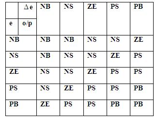
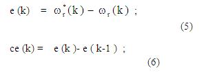
Table I: Linguistic Rule Table
In this paper, the fuzzy sets Z, S, M, L, P, N, PS, PM, PL, NS, NM and NL are defined over the domain of input variables (error and error change) and output variable ( Te).The operation of fuzzy logic is based on the control rules in Table 1. The output of FLC should be a crisp value. The defuzzification process is used to determine a crisp value according to the fuzzy output from inference mechanism. The center-of area method is used as a defuzzification strategy in this paper.
- B) Proposed Neural Network Controller
In this second concept, the controller is represented as a nonlinear map between the inputs and outputs. Depending on a specific plant, the map (in the form of a network) can be trained to implement any kind of control strategy. A neuro-controller (neural networks based control system) performs a specific form of the adaptive control with the controller taking the form of a multi layer network and the adaptable parameters being defined as the adjustable weights. The main advantages are:
(1) Parallel architecture
(2) Any kind of nonlinear mapping is possible
(3) Training is possible for various operating conditions,
so it can be adapted to any desired situation. The simple fuzzy controller represents a good nonlinear controller; however, it cannot adapt its structure whenever the situation demands. Sometimes the fuzzy controllers with fix structures fail to stabilize the plant under wide variations in the operating conditions. These types of controllers also lack the parallelism of neural controllers. On the other hand the neural networks are very much adaptive to situations by adjusting their weightsaccordingly. The parallel architecture enables faster implementation of the control algorithm. However in the presence of noise and other uncertainties the performance may deteriorate. Some times in certain neural controller structures the model of the plant is required.
Figure 4 shows the structure of the proposed neural network controller. The improved BP network contains the input layer, the hidden layer, the output layer, and the connected weight between the input node and the hidden node is wij, the weight between the hidden node and the output node is Tli, θ denotes the threshold. x j isthe input layer neural node, yiis the hidden layer neural node, Olis the output of the neural network, the desired output of output node is tl.
Figure 4Proposed Neural Network Controller
- SIMULATION RESULTS
To verify the technique proposed in this paper, simulations based on Matlab / Simulink have been implemented. The Typical simulation results for the conventional PI controller, Fuzzy PI controller and proposed neural network controller are shown in Figure 5 to8 for the torque and speed responses. For all these simulations the initial conditions are zero. In BLDC using fuzzy logic, speed error and change of speed errorare taken as inputs and torque as the output. As described earlier, membership functions were chosen and rules were formed.Figure 5show the comparison of speed responses between conventional PI and FLC and Figure6 shows the comparison of speed responses between FLC and proposed neural network controller. Figure 7 shows the comparison of speed responses between conventional PI, FLC and proposed neural network controller. From this result, it is observed that, withproposed neural network controller, speed easily attains steady state value at the earlier stage itself when compared to other controllers.
The simulation results shows that speed and torque responses are very good dynamic responses for proposed neural network controller. Figure 8shows the torque ripple reduction and is compared with the conventional PI and FLC. From this result, it is observed that, the torque response in the conventional PI controller presented with the high ripples, whereas in the FLC the ripple content is reduced to some extent. Bythe proposed neural network controller, there are further reduced ripples in torque response.
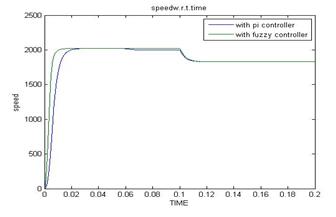
Fig 5.Speed responses of PI and FLC

Fig 6.Speed responses of FLC and Neural network Controller
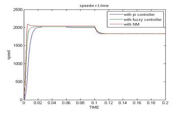
Fig 7.Speed responses of PI, FLC and Neural network Controller
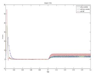
Fig 8.Torque Responses of PI, FLC and Neural network Controller
- CONCLUSIONS
In this paper, the neural networks based controller has been proposed and results have been compared with the conventional PI and fuzzy PI controllers. Among all these controllers, the neural network shows better response. By using this controller, its output is updating in the PI controller gains based on a set of rules to maintain excellent control performance even in the presence of parameter variation and drive non-linearity. This simple scheme has significantly improved the performance of the BLDC system while at the same time maintaining the simple control structure of the BLDC.
References
[1] Y. S. Jeon, H. S. Mok, G. H. Choe, D. K. Kim, and J. S. Ryu, “A New Simulation Model of BLDC Motor With Real Back EMF Waveform”,Computers in Power Electronics, 2000. COMPEL 2000. The 7th Workshop on, pp. 217-220, July 2000.
[2] Lei Hao and Hamid A. Toliyat, “BLDC Motor Full Speed Range Operation Including the Flux – Weakening Region”, Industry Applications Conference, 2003. 38th IAS Annual Meeting.Conference Record of the, vol. 1, pp. 618-624, October 2003.
[3]48531 EMS – Chapter 12. Brushless DC Motors
[4]S. M.M.Mirtalaei, J.S.Moghani, K.Malekian, B.Ab ” A Novel Sensorless Control Strategy for BLDC Motor Drives Using a Fuzzy Logic-based Neural Network Observer”. di978-1-4244-1664-6/08/$25.00 ©2008 IEEE
[5]. Depenbrock, “Direct self-control (DSC) of inverter-fed induction machine”, IEEE Trans. PowerElectron., vol.3, pp. 420-429, Oct. 1988.
[6]D. Casadie, G.Serra and A.Tani (2000) “Implementation Of ADirect Torque Control Algorithm for Induction Motors Based On Discrete Space Vector Modulation”, Power Electronics IEEE Transaction On Power Electronics, Vol 15No 4.
[7]Isao Takashi, Toshishiko Noguchi (1997. Take a look back upon the past decade of direct torque control .IECON 97
[8]C.G.Mei, S.K. Panda, J.X.Xu And K.W.Lim.(1999).Direct Torque Control of induction Motor-Variable switching sectors. Proc.IEEE PEDS.
[9] BOSE, B. K. : Power Electronics and Variable Frequency Drives, IEEE Press, New York, 1997.
[10] YONG, L.—ZHUB, Z. Q.—HOWE, D. : Direct Torque Control of Brushless DC Drives with ReducedTorque Ripple, IEEE Trans. on Industry Applications 41 No. 2 (2005), 599–608.
[11] ASTROM, K. J.—WITTENMARK, B. : Adaptive Control, 2nd Edition, Pearson Education, 1995
[12] B. K. Lee, B. Fahimi, M. Ehsani; “Dynamic Modeling of Brushless DC Motor rives”, European Conference on Power Electronics and Applications (EPE’2001), Austria.
[13] C. Chein, ” Fuzzy Logic in Control Systems: Fuzzy Logic Controller,Part 1-2″,IEEE, Trans. on Systems, Man and Cybernetics,Vol. 20, No. 2, pp. 404-428,March/April 1990.